


1-11 STARTUP
CONFIGURATIONS
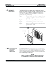
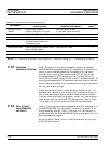
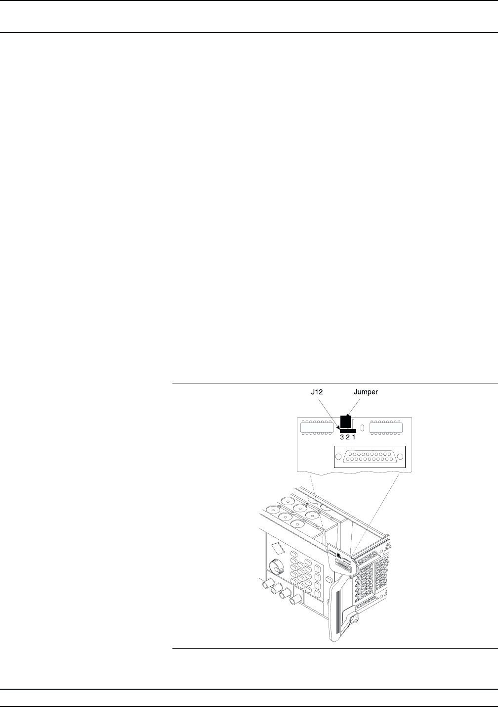
The 682XXB/683XXB comes from the factory with a jumper across
pins 2 and 3 of front panel connector J12 (Figure 1-4). In this configu
-
ration, connecting the instrument to line power automatically places it
in operate mode (front panel OPERATE LED on).
The startup configuration can be changed so that the signal generator
comes up in standby mode (front panel STANDBY LED on) when it is
connected to line power. Change the startup configuration as follows:
Step 1 Disconnect the instrument from line power.
Step 2 Remove the top cover from the 682XXB/683XXB.
(Refer to Chapter 6 for instructions).
Step 3 Locate front panel connector J12 and remove the
jumper from across pins 2 and 3. It is located on the
A2A1 PCB which plugs into the Front Panel Assem
-
bly.
Step 4 Install the jumper across pins 1 and 2 of connector
J12.
Step 5 Install the top cover and connect the signal genera-
tor to line power. The instrument should come up in
standby mode.
682XXB/683XXB MM 1-11
Figure 1-4. Startup Configuration of Connector J12
GENERAL START UP
INFORMATION CONFIGURATION