


Rise/Fall
Time and
Overshoot
The following procedure lets you measure the rise
time, fall time, and overshoot parameters of the
pulse modulation waveform.
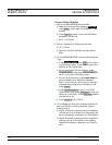
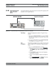
1. Set up the 682XXB/683XXB as follows:
a.
Reset the instrument by pressing SYSTEM ,
then Reset . Upon reset, the CW Menu is dis
-
played.
b.
Press Edit F1 to open the current frequency
parameter for editing.
c. Set F1 to 5.0 GHz.
d.
Press Edit L1 to open the current power level
parameter for editing.
e. Set L1 to the maximum leveled output power
level for the instrument being tested (refer to
Table 3-2, page 3-6).
f.
Press MODULATION , then Pulse . The Inter-
nal Pulse Status menu is displayed.
g. At the Internal Pulse Status menu, press
Edit Width and set pulse width W1 to 5.0 ms.
h.
Press Edit Period and set the PRI to 0.01 ms.
i.
Press On/Off to turn pulse modulation on.
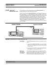
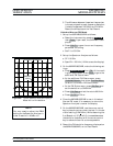
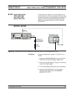
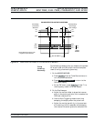
2. On the Oscilloscope, turn off CH.4. Observe the
output of the Pulse Detector on the Oscilloscope.
Refer to Figure 3-11 to interpret the detector
waveform. Adjust the Oscilloscope controls to
measure the following waveform parameters.
a. Rise/Fall Time (10 to 90%): <10 ns
b. Pulse Width: 5 ms ±10 ns (5 ns, typical)
c. PRI: 0.010 ms ±10 ns (5 ns, typical)
d. Overshoot: <10%
3. Record the results on the Test Record.
3-40 682XXB/683XXB MM
PERFORMANCE PULSE MODULATION TESTS:
VERIFICATION RISE TIME, FALL TIME, OVERSHOOT, AND LEVEL