


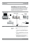
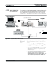
4. Connect the 682XXB/683XXB RF OUTPUT to the
Spectrum Analyzer RF Input.
NOTE
Before beginning this calibration proce
-
dure, always let the 682XXB/683XXB
warm up for a minimum of one hour.
FM
Calibration
Procedure
The following steps in the procedure lets you cali
-
brate the FM Variable Gain Control DAC and the
FM Flatness DAC in both Wide and Narrow FM
modes and store the results in non-volatile memory
(EEPROM) on the A17 CPU PCB.
NOTE
To ensure accurate calibration, each step of
this procedure must be performed in se
-
quence.
1. External Wide FM Mode Sensitivity calibration is
accomplished by adjusting the FM Variable Gain
Control DAC to reduce the carrier level as low as
possible at frequencies of 5 GHz and 20 GHz. The
modulating signal input is from the external
Function Generator.
Perform the calibration as follows:
a.
At the
$ prompt, type: calterm 149 and
press <ENTER>.
b. Set up the Function Generator for a 99.8 kHz
sine wave with an output level of 0.707 volts
RMS (2 volts peak to peak). Use a frequency
counter to verify the output frequency of your
function generator is set to ±1%.
c. On the Spectrum Analyzer, set the Span/Div to
50 kHz per division.
d. On the computer keyboard, use the ‘, 1, 2, and
3 keys to increment and the 7, 8, 9, and 0 keys
to decrement the value of the DAC’s setting.
Start calibration by pressing an increment key.
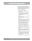
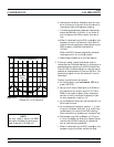
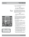
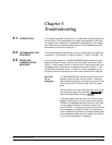
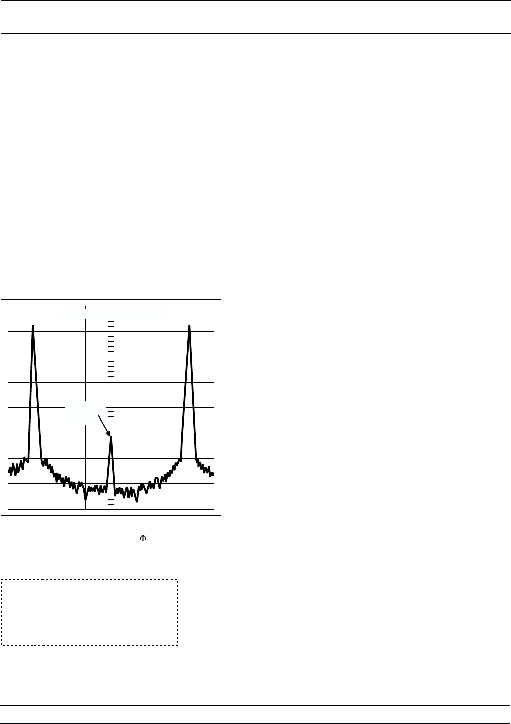
e. While observing the first Bessel null (Figure
4-16) on the Spectrum Analyzer display, adjust
the value of the DAC’s setting to reduce the
carrier level as low as possible.
f.
When finished setting the DAC, press
Q on the
keyboard to go to the next calibration step.
4-52 682XXB/683XXB MM
PHASE MODULATION
CALIBRATION (FM) CALIBRATION
CENTER FREQUENCY
BESSEL
NULL
Figure 4-16. Typical Spectrum Analyzer Display
of Bessel Null on M Waveform
NOTE
You may need to adjust the RBW
setting on the Spectrum Analyzer in
order to see the >–40 dBc null.