4-11 ALC BANDWIDTH
CALIBRATION
This procedure provides the steps necessary to perform ALC Band
-
width calibration. The ALC Bandwidth is adjusted to compensate for
gain variations of the modulator. The adjustment is performed for
each frequency band. This provides a more consistent bandwith
throughout the frequency range of the instrument.
Equipment
Setup
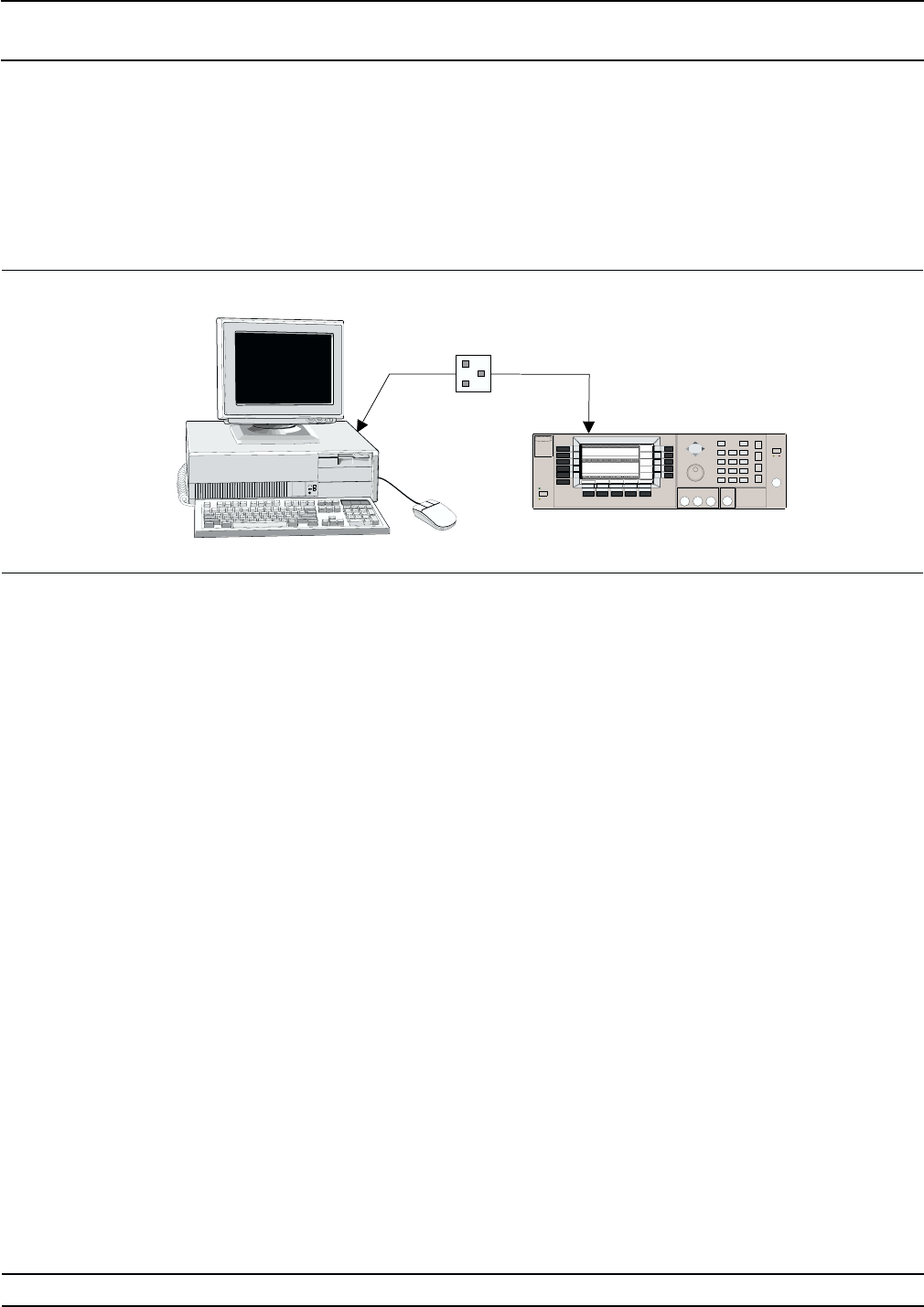
Connect the equipment, shown in Figure 4-9, as fol-
lows:
1. Interface the PC to the 682XXB/683XXB by per-
forming the initial setup procedure, pages 4-7 to
4-12.
NOTE
Before beginning this calibration proce
-
dure, always let the 682XXB/683XXB
warm up for a minimum of one hour.
Bandwidth
Calibration
The following procedure lets you (1) calibrate the
ALC bandwith and (2) store the calibration data in
non-volatile memory (EEPROMs) on the A17 CPU
PCB.
1. Enter the ALC Bandwidth calibration routine as
follows:
a.
At the
$ prompt on the PC display, type:
calterm 110 and press <ENTER>.
The following will appear on the PC display:
Enter calculated gain X.XX
Input:
b.
Type:
1.50 and press <ENTER>.
682XXB/683XXB MM 4-31
ALC BANDWIDTH
CALIBRATION CALIBRATION
Serial
I/O
682XXB / 683XXB
COM1
or
COM2
IBM-Compatible PC
Figure 4-9. Equipment Setup for AM Bandwidth Calibration


