


Normal
Operation
Error and
Warning/
Status
Messages
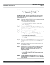
When an abnormal condition is detected during op
-
eration, the 682XXB/683XXB displays an error mes
-
sage to indicate that the output is abnormal or that
a signal input or data entry is invalid. It also dis
-
plays warning messages to alert the operator to
conditions that could cause an inaccurate signal
generator output. Status messages to remind the
operator of current menu selections or settings are
also generated.
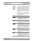
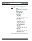
Table 5-2 is a summary list of possible error mes
-
sages that can be displayed during normal opera
-
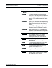
tions. Table 5-3 is a summary list of possible
warning/status messages.
682XXB/683XXB MM 5-7
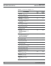
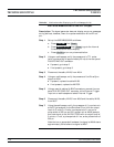
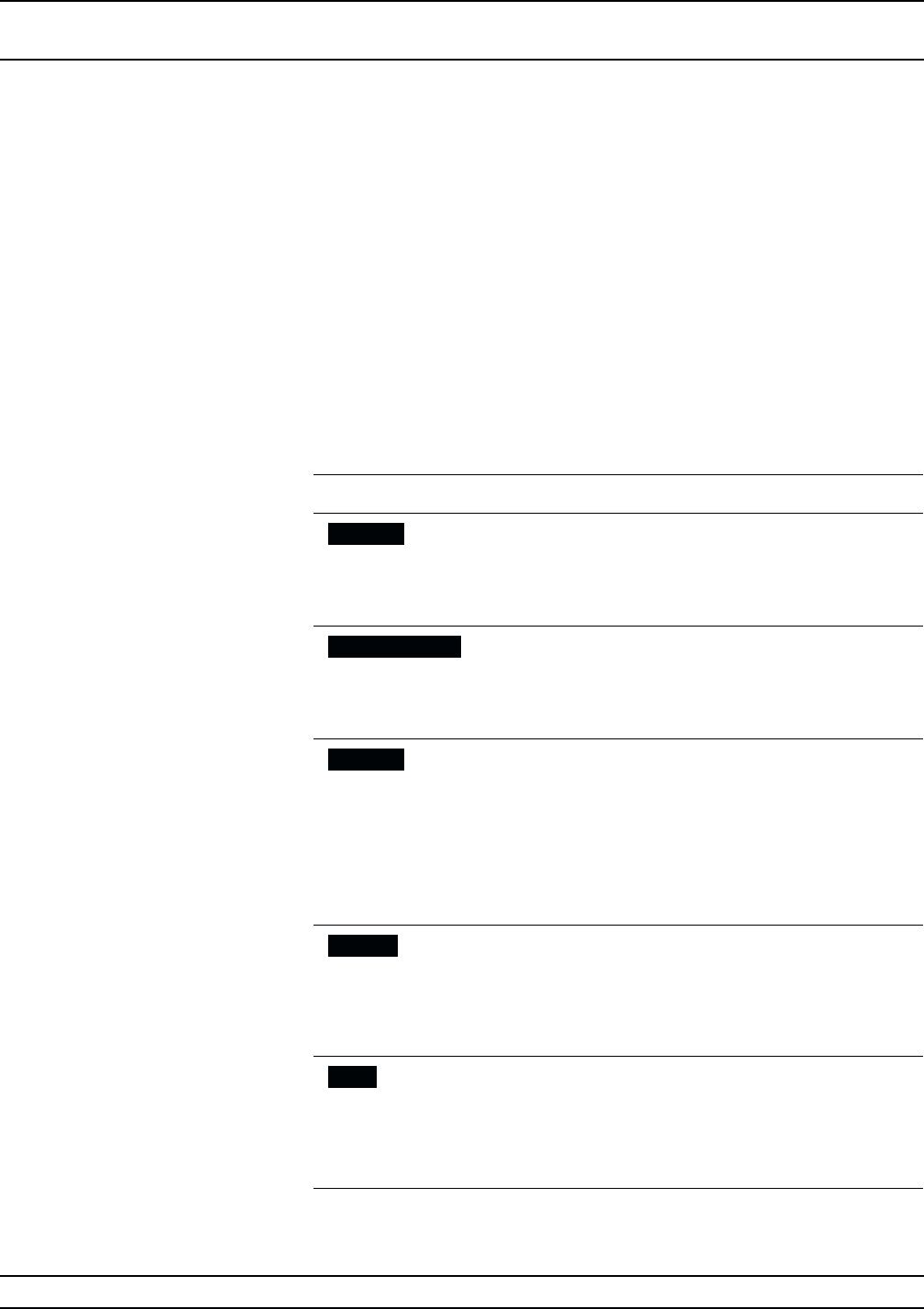
Error Message Description
ERROR
Displayed (on the frequency mode title bar) when (1) the
output frequency is not phase-locked, (2) an invalid
frequency parameter entry causes a frequency range
error, or (3) an invalid pulse parameter entry causes a
pulse modulation error.
LOCK ERROR
Displayed (in the frequency parameters area) when the
output frequency is not phase-locked. The frequency
accuracy and stability of the RF output is greatly reduced.
Normally caused by an internal component failure. Run
self-test to verify malfunction.
RANGE
Displayed (in the frequency parameters area) when (1)
the analog sweep start frequency entered is greater than
the stop frequency (683XXB models only), (2) the dF
value entered results in a sweep outside the range of the
instrument, (3) the step size value entered is greater than
the sweep range, or (4) the number of steps entered
results in a step size of less than 1 kHz (0.1 Hz with
Option 11) or 0.1 dB. Entering valid values usually clears
the error.
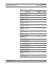
SLAVE
Displayed (in the frequency parameters area of the
Master 68XXXB) during master-slave operation in VNA
mode when the slave frequency offset value entered
results in a CW frequency or frequency sweep outside the
range of the slave 68XXXB. Entering a valid offset value
clears the error.
ERR
Displayed (in the modulation status area) when one or
more of the following error conditions occurrs:
(1) The external AM modulating signal exceeds the input
voltage range. In addition, the message “Reduce AM
Input Level” appears at the bottom of the AM status
display. (Continued on next page)
Table 5-2. Possible Error Messages during Normal Operations (1 of 2)
ERROR AND WARNING/
TROUBLESHOOTING STATUS MESSAGES