


NOTE
If the 682XXB/683XXB LO output is less
than 10 dBm, the Mixer’s local oscillator
port will not be saturated and the resulting
measurements may be in error.
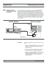
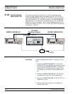
3. Set up the Spectrum Analyzer as follows:
a. Center Frequency: 1 MHz
b. Frequency Span: 300 Hz
c. RBW: 3 Hz
d. Position the Marker to the peak of the signal.
e. Select OFFSET, ENTER OFFSET, and
MKRCF.
f. Adjust the marker for a 100 Hz offset.
g. Select NOISE LVL.
4. Measure the phase noise level 100 Hz offset from
the carrier frequency. Record the level on the Test
Record.
5. On the Spectrum Analyzer:
a. Deselect NOISE LVL.
b. Set Frequency Span to 20 kHz.
c. Set RBW to 100 Hz.
d. Adjust the Marker for a 1 kHz offset.
e. Select NOISE LVL.
6. Measure the phase noise level 1 kHz offset from
the carrier frequency. Record the level on the Test
Record.
7. On the Spectrum Analyzer:
a. Deselect NOISE LVL.
b. Set Frequency Span to 100 kHz.
c. Adjust the Marker for a 10 kHz offset.
d. Select NOISE LVL.
8. Measure the phase noise level 10 kHz offset from
the carrier frequency. Record the level on the Test
Record.
3-24 682XXB/683XXB MM
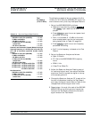
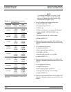
PERFORMANCE SINGLE SIDEBAND
VERIFICATION PHASE NOISE TEST
CW Carrier
Frequency
Offset From
Carrier
Test
Specification*
0.6 GHz
100 Hz
1 kHz
10 kHz
100 kHz
<–74 dBc
<–85 dBc
<–83 dBc
<–97 dBc
0.6 GHz
(68XX5B)
100 Hz
1 kHz
10 kHz
100 kHz
<–84 dBc
<–97 dBc
<–95 dBc
<–112 dBc
2.0 GHz
100 Hz
1 kHz
10 kHz
100 kHz
<–77 dBc
<–85 dBc
<–83 dBc
<–99 dBc
2.0 GHz
(68XX5B)
100 Hz
1 kHz
10 kHz
100 kHz
<–78 dBc
<–91 dBc
<–89 dBc
<–106 dBc
6.0 GHz
100 Hz
1 kHz
10 kHz
100 kHz
<–75 dBc
<–85 dBc
<–83 dBc
<–99 dBc
10.0 GHz
100 Hz
1 kHz
10 kHz
100 kHz
<–70 dBc
<–83 dBc
<–80 dBc
<–99 dBc
20.0 GHz
100 Hz
1 kHz
10 kHz
100 kHz
<–63 dBc
<–75 dBc
<–75 dBc
<–97 dBc
26.5 GHz
100 Hz
1 kHz
10 kHz
100 kHz
<–60 dBc
<–75 dBc
<–73 dBc
<–93 dBc
Table 3-5. Single Sideband Phase Noise
Test Specification
* 3 dB difference from 682XXB/683XXB single side
-
band phase noise specifications to account for LO
phase noise.