


682XXB/683XXB MM 5-47
TROUBLESHOOTING
TROUBLESHOOTING TABLES
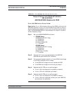
Error 130 2-3.3 GH Switched Filter
Error 131 3.3-5.5 GH Switched Filter
Error 132 5.5-8.4 GH Switched Filter
Error 133 8.4-13.25 GH Switched Filter
Error 134 13.25-20 GH Switched Filter
Description: Each of these error messages indicates a failure in a
switched filter path within the switched filter assembly. The 682XXB/
683XXB may or may not produce an RF output in the frequency range of
the failed switched filter path.
Step 1. Set up the 682XXB/683XXB as follows:
a.
682XXB Setup:
CW/SWEEP SELECT: Step
F1: 2.000 GHz
F2: 20.000 GHz
Number of Steps: 400
683XXB Setup:
CW/SWEEP SELECT: Analog
F1: 2.000 GHz
F2: 20.000 GHz
Sweep Time: 0.100 Sec
Step 2. Connect the X input of an oscilloscope to the 682XXB/
683XXB rear panel HORIZ OUT connector.
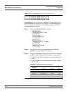
Step 3. Using the oscilloscope, check for the switched filter PIN
switch drive voltages at the test points shown in Table 5-21.
If the PIN switch drive voltages are correct, replace the
switched filter assembly.
If the PIN switch drive voltages are incorrect, replace the
A9 PCB.
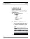
Table 5-20. Error Messages 128, 129, 130, 131, 132, 133, 134, and 135 (7 of 8)
Test Point
Active Frequency
Range
Active
Voltage
Inactive
Voltage
A9TP18 2 to 3.3 GHz –2V +1V
A9TP10 3.3 to 5.5 GHz –2V +1V
A9TP12 5.5 to 8.4 GHz –2V +1V
A9TP16 8.4 to 13.25 GHz –2V +1V
A9TP21 13.25 to 20 GHz –2V +1V
A9TP17 2 to 8.4 GHz –2V +2V
Table 5-21. Switched Filter PIN Switch Drive Voltages