


3-12 AMPLITUDE
MODULATION TEST
This procedure verifies the operation of the 682XXB/683XXB ampli
-
tude modulation input sensitivity circuit.
The RF OUTPUT of the 682XXB/683XXB is monitored on a Spectrum
Analyzer display. The (modulated) IF Output of the Spectrum Ana
-
lyzer is monitored with a Modulation Analyzer. A 50% AM (default
value) signal is set to a reference point on the Spectrum Analyzer. The
actual modulation value is then computed from the indicated Modula
-
tion Meter values. (The absolute values of the AM PK+ and AM PK–
readings are used in the given formula to compensate for non-linearity
errors in the test equipment.)
Test Setup
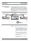
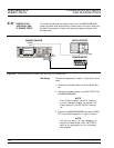
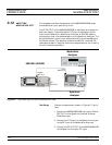
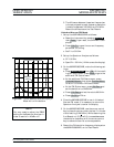
Connect the equipment, shown in Figure 3-7, as fol
-
lows:
1. Connect the 682XXB/683XXB rear panel 10 MHz
REF OUT to the Spectrum Analyzer External
Reference Input.
2. Connect the IF Output of the Spectrum Analyzer
to the RF Input of the Modulation Analyzer.
3. Connect the RF OUTPUT of the 682XXB/683XXB
to the Spectrum Analyzer RF Input.
3-30 682XXB/683XXB MM
682XXB / 683XXB
RF
OUTPUT
10 MHz
REF OUT
EXT
REF Input
RF Input
RF Input
IF Output
Modulation
Analyzer
Spectrum
Analyzer
Figure 3-7. Equipment Setup for Amplitude Modulation Tests
PERFORMANCE AMPLITUDE
VERIFICATION MODULATION TEST