


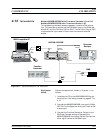
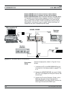
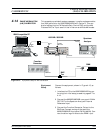
4. Connect the 682XXB/683XXB RF OUTPUT to the
Spectrum Analyzer RF Input.
NOTE
Before beginning this calibration proce
-
dure, always let the 682XXB/683XXB
warm up for a minimum of one hour.
FM
Calibration
Procedure
The following steps in the procedure lets you cali
-
brate the (1) FM Meter circuit; (2) FM Variable Gain
Linearity; (3) Locked, Locked Low-Noise, Unlocked
Narrow, and Unlocked Wide FM Mode Sensitivity;
and (4) FM Rear Panel Input Gain, and store the re
-
sults in non-volatile memary (EEPROM) on the A17
CPU PCB.
NOTE
To ensure accurate calibration, each step of
this procedure must be performed in se-
quence.
1. Perform FM Meter calibration as follows:
a.
At the
$ prompt on the PC screen, type:
calterm 123 and press <ENTER>.
b. Set up the Function Generator for a 100.0 kHz
sine wave with an output level of 0.707 volts
±0.01 volts RMS (2 volts peak to peak). Use a
frequency counter to verify the output fre
-
quency of your function generator is set to
±1%. When done, press any key on the key
-
board to continue calibration.
The
$ prompt will appear on the screen when
the calibration is complete.
c. Record step completion on the Test Record.
2. Perform FM Variable Gain Linearity calibration
as follows:
a.
At the
$ prompt on the PC screen, type:
calterm 148 and press <ENTER>.
b. Set up the Function Generator for a +1.00 Vdc
output. When done, press any key on the key
-
board to continue calibration.
The
$ prompt will appear on the screen when
the calibration is complete.
c. Record step completion on the Test Record.
682XXB/683XXB MM 4-45
FM
CALIBRATION CALIBRATION
NOTE
To save the calibration data after
completing any calibration step,
type:
calterm 787 and press
<ENTER>.