


0.5 - 2.2 GHz
Test
Procedure
The following procedure lets you measure the 0.5 to
2.2 GHz RF output harmonic levels to verify that
they meet specifications.
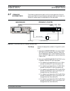
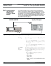
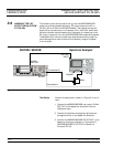
1. Set up the 682X5B/683X5B as follows:
a.
Reset the instrument by pressing SYSTEM ,
then Reset . Upon reset the CW Menu is dis
-
played.
b.
Press Edit L1 to open the current power level
parameter for editing.
c. Set L1 to the lesser of +10 dBm or the maxi
-
mum leveled power level for the instrument
being tested (refer to Table 3-2, page 3-6).
d.
Press Edit F1 to open the current frequency
parameter for editing.
e. Set F1 to the frequency indicated on the Test
Record.
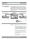
2. Set up the Spectrum Analyzer as follows:
a. Span: 5 kHz/div
b. CF: Set to the 682X5B/683X5B frequency
value.
c. RBW: 1 kHz
d. Video Filter Wide: On
3. Adjust the Spectrum Analyzer Peaking control
for maximum signal level, then adjust the Refer
-
ence Level Control to place the signal at the top
of the screen graticule.
4. Change the Spectrum Analyzer CF to each of the
harmonic frequencies listed on the Test Record
and record the signal levels on the Test Record.
Refer to Table 3-3 (page 3-15) for the specified
harmonic signal level limits.
5. Repeat steps 1 through 4 for each of the 682X5B/
683X5B CW carrier and harmonic frequencies
listed on the Test Record. Record the harmonic
signal levels on the Test Record.
682XXB/683XXB MM 3-17
PERFORMANCE SPURIOUS SIGNALS TEST: RF OUTPUT SIGNALS
VERIFICATION £2 GHz (£2.2 GHz for 68XX5B MODELS)