


4-6 682XXB/683XXB MM
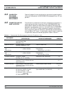
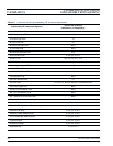
Subassembly/RF Component Replaced
Perform the Following
Calibration(s) in Paragraph(s):
A1, A2 Front Panel Assy None
A3 Reference Loop PCB 4-7
A4 Coarse Loop PCB 4-7
A5 Fine Loop PCB 4-7
A6 Pulse Generator PCB None
A7 YIG Loop PCB None
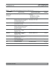
A8 Function Generator PCB 4-12
A9 PIN Control PCB 4-8, 4-9, 4-10, 4-11
A10 ALC PCB 4-8, 4-9, 4-10, 4-11, 4-12
A11 FM PCB 4-13 (and 4-14 if Option 6 is installed)
A12 Analog Instruction PCB 4-7
A13 YIG Driver PCB 4-7
A14 SDM, SQM Driver PCB 4-9, 4-10, 4-11
A15 Regulator PCB None
A16 CPU Interface PCB 4-7
A17 CPU PCB 4-7 thru 4-13. None, if calibration EEPROM reused.
A18 Power Supply PCB None
A19 AC Line Conditioner PCB None
A21 Line Filter/Rectifier PCB None
A21-1 BNC/Aux IO Connector PCB None
YIG-tuned Oscillator 4-7
0.01 to 2 GHz Down Converter Assy 4-8, 4-9, 4-10, 4-11
0.5 to 2.2 GHz Digital Down Converter Assy 4-8, 4-9, 4-10, 4-11
Switched Filter Assy 4-8, 4-9, 4-10, 4-11
Switched Doubler Module (SDM) 4-8, 4-9, 4-10, 4-11
Source Quadrupler Module (SQM) 4-8, 4-9, 4-10, 4-11
Forward Coupler 4-8, 4-9, 4-10, 4-11
Directional Coupler 4-8, 4-9, 4-10, 4-11
Step Attenuator 4-8, 4-9, 4-10
Table 4-2. Calibration Following Subassembly/RF Component Replacement
CALIBRATION FOLLOWING
CALIBRATION SUBASSEMBLY REPLACEMENT