


Models 683XXB with Firmware Version 2.00 and above
(Models 683X5B with Firmware Version 1.00 and above)
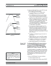
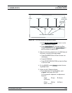
This procedure provides the steps necessary to perform ALC Slope
calibration. The ALC Slope is calibrated to adjust for decreasing out
-
put power-vs-output frequency in full band analog sweep.
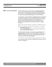
Equipment
Setup
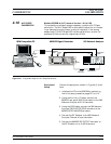
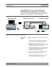
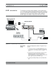
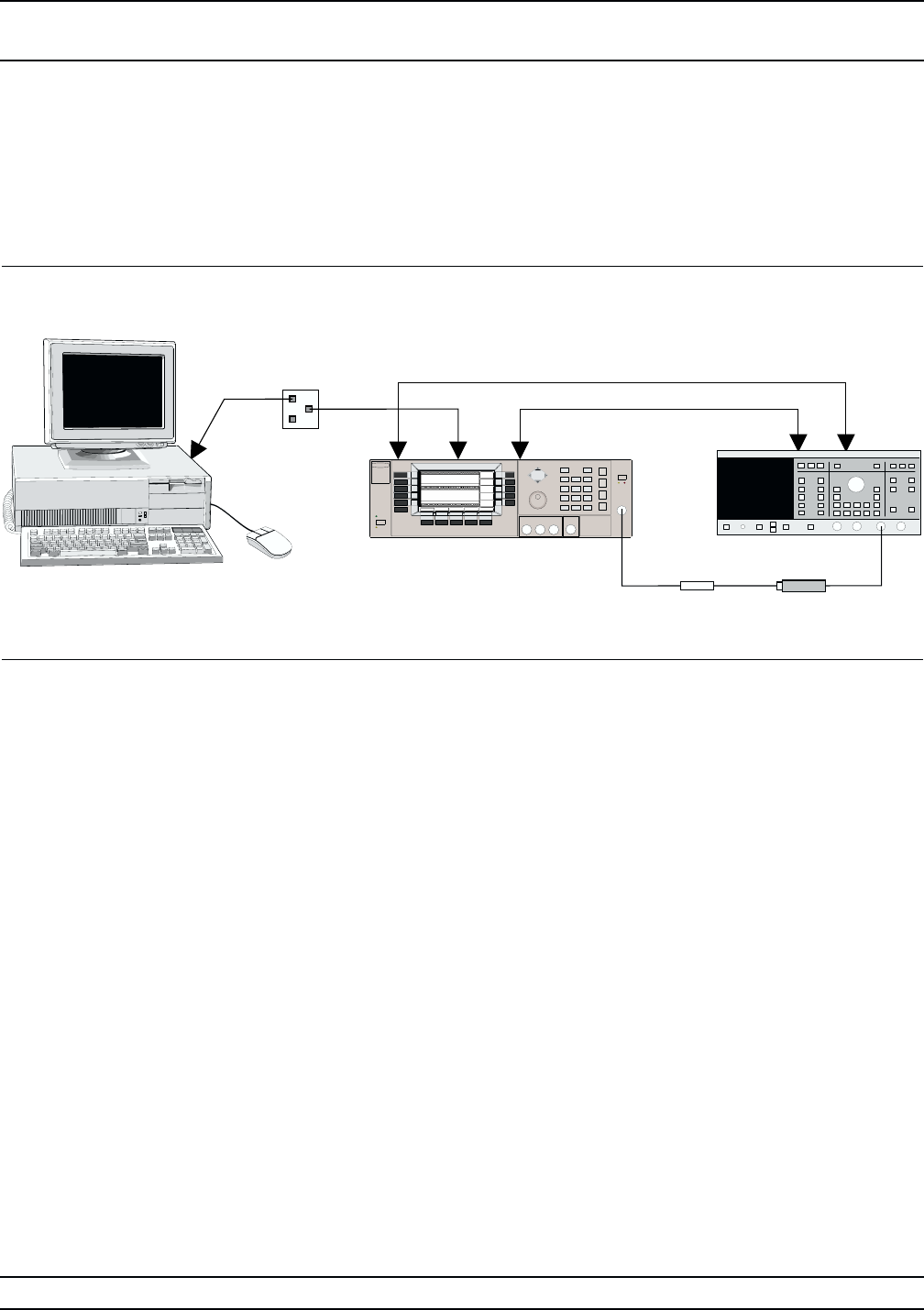
Connect the equipment, shown in Figure 4-7, as fol-
lows:
1. Interface the PC to the 683XXB by performing
the initial setup procedure, pages 4-7 to 4-12.
2. Using the Auxiliary I/O cable, connect the
683XXB rear panel AUX I/O connector to the 562
Network Analyzer AUX I/O connector.
3. Using the GPIB cable, connect the 562 Network
Analyzer DEDICATED GPIB connector to the
683XXB IEEE-488 GPIB connector.
4. Connect the RF Detector to the 562 Network
Analyzer Channel A Input connector.
5. Connect the 683XXB RF OUTPUT connector to
the RF Detector via a 10 dB Attenuator.
682XXB/683XXB MM 4-27
ALC SLOPE
CALIBRATION CALIBRATION
Serial
I/O
683XXB Signal Generator
COM1
or
COM2
IBM-Compatible PC 562 Network Analyze
r
10 dB
Attenuator
GPIB
AUX
I/O
RF Detector
Dedicated
GPIB
RF
Output
A
AUX
I/O
Figure 4-7. Equipment Setup for ALC Slope Calibration