c. Press CHANNEL 2 DISPLAY: OFF.
d. Press CHANNEL 1 DISPLAY: ON.
e. Press CHANNEL 1 MENU key.
f. From the Channel 1 Menu display, select
POWER.
g. Press OFFSET/RESOLUTION.
b. Set Resolution to 5 dB/Div.
c. Adjust Offset to center the display.
2. Adjust the Switched Filter Shaper DAC for each
of the frequency bands as follows:
a.
At the
$ prompt on the PC display, type:
calterm 138 and press <ENTER>.
NOTE
At the start of each frequency band, there
will be a delay while the minimum unlev-
eled power point is determined.
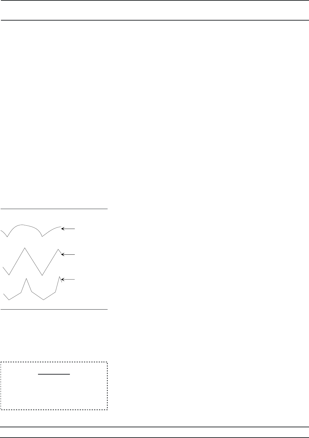
b. On the computer keyboard, use 1, 2, or 3 to in-
crement and 8, 9, or 0 to decrement the value
of the DAC’s setting to adjust the triangle
waveform being displayed on the 562 Network
Analyzer (Figure 4-5) for the most linear re-
sponse.
There will be a delay while the amplifier com
-
pression point is determined and after each
key stroke as the DAC is adjusted.
c. When the DAC has been adjusted for the cur
-
rent frequency band, press
Q on the keyboard
to go to the next frequency band.
d. Repeat steps b. and c. until the DAC has been
adjusted for all frequency bands.
e.
Press
Q on the keyboard to exit the program.
(The
$ prompt will appear on the screen.)
f. Record step completion on the Test Record.
3. Store the calibration data in non-volatile memory
(EEPROMs) on the A17 CPU PCB as follows:
a.
Type:
calterm 787 and press <ENTER>.
(The
$ prompt will appear on the screen when
the data has been stored.)
b. Record step completion on the Test Record.
4-20 682XXB/683XXB MM
SWITCHED FILTER
CALIBRATION SHAPER CALIBRATION
CAUTION
When saving calibration data, turn
-
ing off the instrument before the
$
prompt returns to the screen can
cause all stored data to be lost.
Decrement
DAC
Setting
Correctly
Adjusted
Increment
DAC
Settings
Figure 4-5. Shaper DAC Adjustment
Waveform Examples


