


Workman e2050/e2065 Page 5 – 13 Chassis (Rev. B)
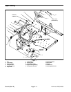
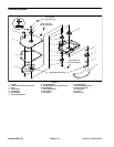
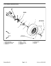
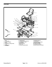
Removal (Fig. 5)
1. Park vehicle on a level surface, turn on/off switch
OFF, set parking brake and remove key from the on/off
switch.
WARNING
Before jacking up the machine, review and follow
Jacking Instructions in Operator’s Manual and
Chapter 1 – Safety.
2. Chock wheels not being jacked up. Jack front wheel
off the ground and place blocks beneath the frame.
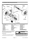
3. Remove front wheel assembly as follows:
A. Remove dust cap carefully from the wheel to pre-
vent damage to the cap.
B. Remove cap screw and two (2) washers that se-
cure the wheel assembly to the spindle. Slide wheel
assembly from the spindle shaft.
4. Remove spindle as follows:
A. Remove cotter pin and slotted hex nut that secure
tie rod ball joint to the spindle. Separate ball joint from
the spindle.
B. If necessary, remove tie rod from Pitman arm.
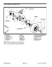
C. Remove lock nut and cap screw (king pin) secur-
ing the spindle to the A–arm. Separate spindle from
the A–arm. Locate and retrieve thrust washer (item
13).
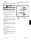
Installation (Fig. 5)
1. Install spindle as follows:
A. Position king pin sleeve into the pivot hub of the
A–arm. Spacer must extend through the bottom of
the hub.
B. Place thrust washer onto the bottom of the king
pin sleeve. Then position spindle over the hub, king
pin sleeve and thrust washer.
NOTE: Make sure cap screw (king pin) is inserted down
through the spindle and A–arm hub.
C. Secure spindle to A–arm hub with cap screw
(king pin) and lock nut. Torque lock nut from 75 to 100
ft–lb (102 to 136 N–m).
D. If tie rod was removed from Pitman arm, insert tie
rod ball joint up through Pitman arm and secure with
slotted hex nut.
E. Insert tie rod ball joint down through the spindle.
Secure with slotted hex nut.
F. Torque slotted hex nut(s) from 20 to 25 ft–lb (27 to
34 N–m) to secure ball joint to spindle (and Pitman
arm, if installed). If necessary, tighten nut to allow
cotter pin to be inserted. Install cotter pin to secure
assembly.
2. Install front wheel assembly:
A. Place antiseize lubricant on spindle shaft.
B. Slide wheel assembly onto spindle shaft with the
valve stem facing out.
NOTE: Apply Loctite #242 (or equivalent) to the
threads of the cap screw.
C. Place large washer and then small washer onto
the cap screw. Thread cap screw with washers into
the spindle shaft.
D. Torque cap screw from 135 to 165 ft–lb (183 to
224 N–m).
3. Lower machine to ground. Remove chocks from
wheels.
4. Align steering and toe–in (see Operator’s Manual).
5. Lubricate tie rod ball joints and king pin (see Opera-
tor’s Manual).
Chassis