


Workman e2050/e2065
Page 3 – 3
Electrical System (Rev. B)
General Information
The Workman e2050 and e2065 use a 48 volt DC elec-
trical system that is an isolated circuit. The vehicle frame
is not used for any ground connections.
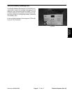
The vehicle controller monitors operator and vehicle in-
puts to determine voltage to the traction motor. If a prob-
lem exists that will prevent normal vehicle operation, an
LED on the controller and the vehicle status light on the
dash panel will flash a fault code to assist in identifying
the problem.
After performing any repair on electrical components on
the vehicle, make sure that wiring is routed and secured
so as to prevent abrasion or contact with moving parts.
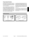
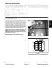
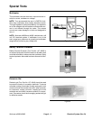
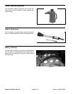
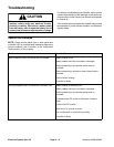
Opening Battery Circuit
To prevent allowing a current path through tools used
during vehicle electrical circuit repairs, remove one of
the battery cables from the battery pack as the first step
in any repair (Fig. 1). Once a cable has been removed,
the electrical system on the vehicle can be safely
worked on. Take care during repairs, however, to not al-
low tools or vehicle components to complete the battery
circuit that was opened with the cable removal.
Reattach the removed cable to the battery pack as the
last step in any repair. Secure cable on each battery ter-
minal with lock washer and nut. Torque nuts from 115 to
125 in–lb (13 to 14.1 N–m).
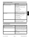
Battery pack cable routing is shown in Figure 2.
Figure 1
1. Negative cable to vehicle 2. Positive cable to vehicle
Figure 2
A
4
1
2
Electrical
System