


Workman e2050/e2065 Transaxle and Brakes (Rev. B)Page 4 – 23
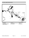
Removal (Fig. 13)
1. Park vehicle on a level surface, turn on/off switch
OFF, set parking brake and remove key from switch.
2. Remove cargo bed from vehicle (see Cargo Bed Re-
moval in Service and Repairs section of Chapter 5 –
Chassis).
3. Open the battery circuit by carefully removing one of
the battery cables (see Opening Battery Circuit in the
General Information section of Chapter 3 – Electrical
System).
NOTE: Label all electrical leads for reassembly pur-
poses.
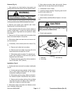
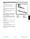
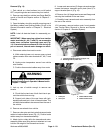
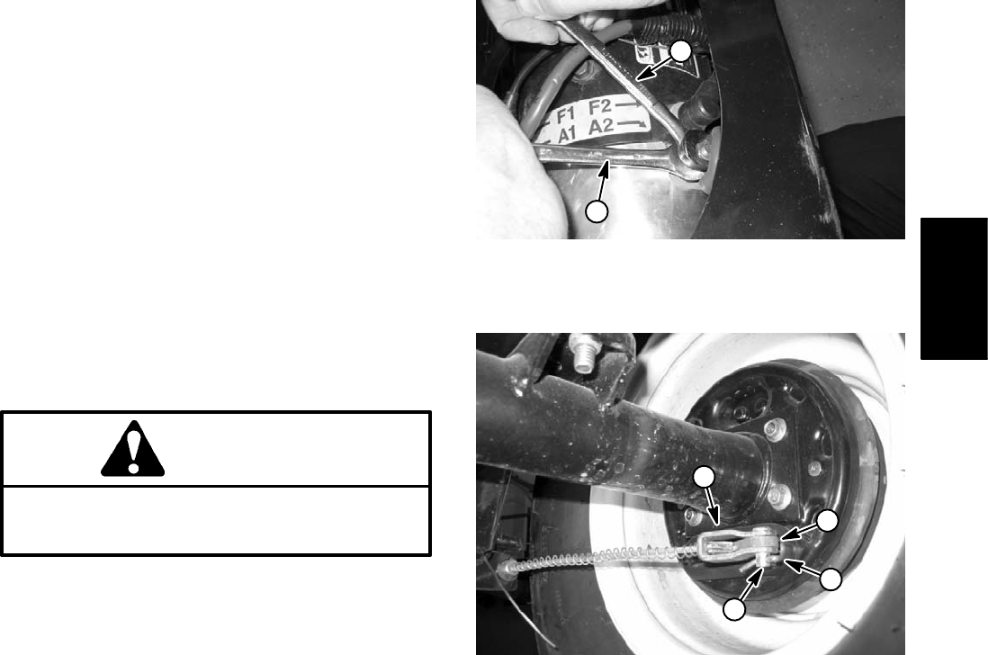
IMPORTANT: When removing cables from traction
motor terminals (A1, A2, F1 and F2), use a wrench to
retain lower nut before loosening upper nut (Fig.
14). If terminal studs are allowed to turn during up-
per nut removal, internal motor damage can occur.
4. Disconnect cables from traction motor:
A. While retaining lower nut, remove upper nut and
cable connector from motor terminals A1, A2, F1 and
F2.
B. Unplug motor temperature sensor from vehicle
wire harness.
C. Position disconnected cables away from motor.
WARNING
Before jacking up the vehicle, review and follow
Jacking Instructions in Operator’s Manual and in
Chapter 1 – Safety.
5. Jack up rear of vehicle enough to remove rear
wheels.
A. Chock the front and rear of both front tires to pre-
vent the vehicle from moving.
B. Support both sides of the rear frame with jack-
stands positioned just in front of the axle tubes. This
will allow the transaxle to be removed from the rear of
the vehicle.
6. Remove rear wheels from vehicle.
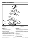
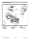
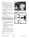
7. Remove cotter pins and clevis pins that secure brake
cables to brake actuator levers (Fig. 15). Position brake
cables away from transaxle assembly.
8. Attach hoist or chain fall to the transaxle and motor
assembly. Make sure lifting device is attached so it can
hold the full weight of the transaxle and motor.
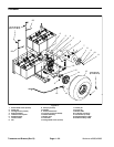
9. Loosen and remove two (2) flange nuts and carriage
screws that secure transaxle mount plate (item 5) to
support bracket (item 4) (Fig. 16).
10.Remove four (4) flange head screws and flange nuts
securing the transaxle to the rear frame.
11.Carefully lower transaxle and motor assembly from
the rear of the vehicle.
12.If necessary, remove traction motor from transaxle
(see Traction Motor Removal in Service and Repairs
section of Chapter 3 – Electrical System).
1. Loosening/tightening wrench (upper nut)
2. Retaining wrench (lower nut)
Figure 14
2
1
1. Cotter pin
2. Clevis pin
3. Brake cable bracket
4. Brake actuator lever
Figure 15
2
3
4
1
Transaxle and
Brakes