


Workman e2050/e2065
Page 3 – 26
Electrical System (Rev. B)
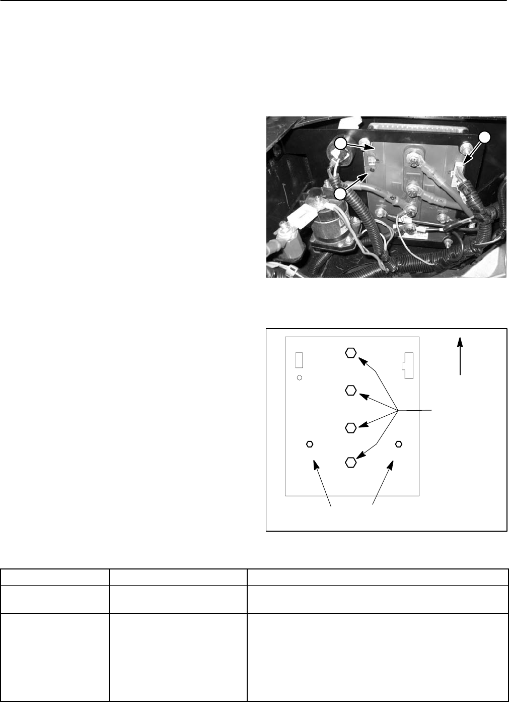
Controller
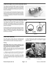
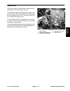
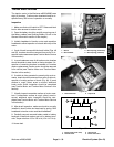
The Workman controller is secured to the rear frame un-
der the controller cover beneath the bed (Fig. 41). The
controller uses inputs from several vehicle switches (on/
off, forward/reverse, accelerator pedal, supervisor,
charger interlock, motor temperature, accelerator po-
tentiometer) to accurately control vehicle speed, vehicle
direction (forward and reverse) and regenerative brak-
ing. An internal thermal sensor prevents overheating of
the controller.
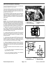
Cable connections for the controller are as follows:
Terminal B–: Negative (–) battery cable and wire
harness ground.
Terminal B+: Positive (+) cable from main contac-
tor post and wire harness fusible link (FL3).
Terminal M1: Cable to traction motor armature A2
post.
Terminal M2: Cable to traction motor armature A1
post.
Terminal F1: Cable to traction motor field F1 post.
Terminal F2: Cable to traction motor field F2 post.
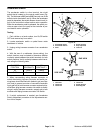
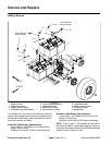
When installing cables to controller, torque screws at
terminals B–, B+, M1 and M2 from 85 to 90 in–lb (9.6 to
10.2 N–m) and torque screws at terminals F1 and F2
from 55 to 60 in–lb (6.2 to 6.8 N–m) (Fig. 42). Apply Toro
battery terminal protector (see Special Tools) to control-
ler connections after tightening terminal screws.
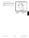
If wire harness connector is removed from controller,
both harness connector and controller socket should be
filled with dielectric gel to prevent corrosion of connec-
tion terminals and potential controller damage. Apply
gel fully to both harness connector and controller sock-
et, plug harness connector into controller to distribute
gel, unplug harness connector, reapply gel to both sur-
faces and plug harness connector into controller.
A LED exists on the controller to identify normal opera-
tion or faults that will prevent the vehicle from operating
correctly. The vehicle status light on the dash panel dis-
plays the same information as the LED on the controller.
See chart below for light pattern fault codes identified by
the controller LED and vehicle status light.
NOTE: If the controller LED and vehicle status light are
flashing, attempt to reset the controller by turning the
On/Off switch to OFF, waiting a few seconds and then
turning the switch to ON. If LED and status light continue
flashing, proceed with fault code identification and nec-
essary action.
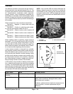
1. Controller
2. Controller LED
3. Wire harness connector
Figure 41
1
2
3
Figure 42
F1 F2
M1
M2
B+
B–
UP
55 to 60 in–lb
(6.2 to 6.8 N–m)
85 to 90 in–lb
(9.6 to 10.2 N–m)
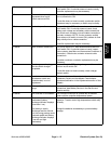
Light Pattern Cause Necessary Action
Always on (not
flashing)
System functioning correctly. None
Always off System inoperable. Check for low battery voltage, faulty fuse(s), loose
battery cable connections, damaged battery cables
and/or faulty main contactor.
If batteries, cables and other electrical components are
in good condition, controller replacement may be
necessary.