


Workman e2050/e2065
Page 3 – 11
Electrical System (Rev. B)
Adjustments
Accelerator Switch Adjustment
1. Position vehicle on a level surface, turn On/Off
switch OFF and remove key. Apply parking brake.
2. Make sure that at complete brake pedal travel, the
park detent and pawl are fully engaged. If needed, ad-
just the accelerator pedal stop cap screw to allow full en-
gagement (Fig. 11).
3. Disengage the parking brake.
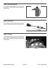
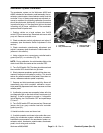
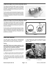
4. With the accelerator pedal released, check that the
distance between the head of the accelerator switch
stop cap screw and the body of the switch is 5/8 inch (1.6
cm) (Fig. 12).
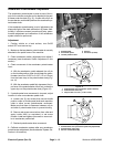
5. If distance is incorrect, loosen lock nut and adjust ac-
celerator switch stop cap screw position (Fig. 11).
6. After adjustment, make sure that switch plunger is
not bottomed out when accelerator pedal is released.
7. After adjustment to switch stop cap screw, make
sure that the switch does not open when the parking
brake is engaged. Readjust switch stop cap screw if re-
quired.
8. Calibrate accelerator system after adjusting acceler-
ator switch (see Accelerator System Calibration in this
section).
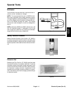
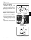
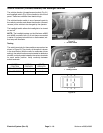
1. Accelerator pedal
2. Accelerator switch
3. Plate
4. Screw (2 used)
5. Switch stop cap screw
6. Lock nut
Figure 10
1
2
3
4
5
6
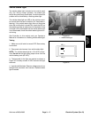
1. Accelerator switch
2. Switch stop cap screw
3. Accelerator stop cap screw
Figure 11
2
1
3
1. Switch stop cap screw 2. Accelerator switch
Figure 12
5/8 inch
(1.6 cm)
1
2
Electrical
System