


Workman e2050/e2065
Transaxle and Brakes (Rev. B)
Page 4 – 18
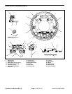
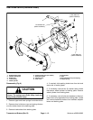
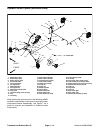
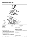
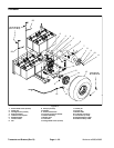
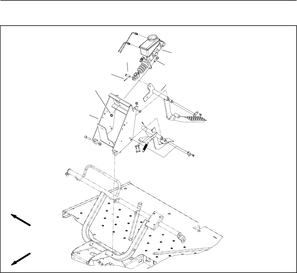
Brake Master Cylinder (Workman e2065)
1. Master cylinder
2. Cap screw
3. Brake pedal
4. Clevis pin
5. Cotter pin
6. Flange head nut
7. Pedal frame
Figure 10
7
3
5
6
2
1
4
FRONT
RIGHT
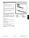
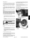
Removal (Fig. 10)
1. Remove front hood from machine.
2. Remove cotter pin from the clevis pin that connects
master cylinder to brake pedal.
3. Clean hydraulic brake line area of master cylinder to
prevent contamination. Remove both brake lines from
master cylinder. Cap ends of brake lines and position
them away from master cylinder.
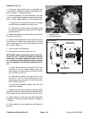
4. Remove flange head nuts from cap screws that se-
cure master cylinder to pedal frame.
5. Pull master cylinder from machine.
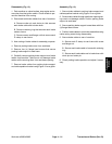
Installation (Fig. 10)
1. Position master cylinder to pedal frame and secure
with cap screws and flange nuts.
2. Remove plugs from brake lines. Install brake lines to
master cylinder.
3. Connect master cylinder to brake pedal with clevis
pin and cotter pin.
4. Install front hood to machine.
5. Bleed brakes (see Bleed Brake System in this chap-
ter). Check brake operation.