


Workman e2050/e2065
Page 3 – 34
Electrical System (Rev. B)
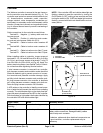
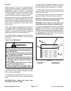
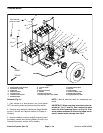
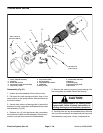
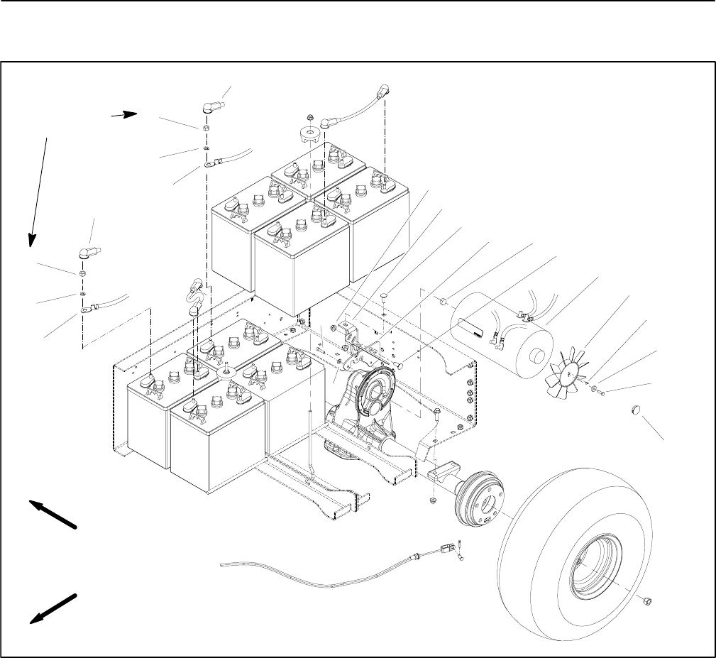
Traction Motor
1. Socket head screw (6 used)
2. Flat washer (6 used)
3. Flange nut
4. Support bracket
5. Carriage screw
6. Transaxle mount plate
7. Rubber damper
8. Traction motor
9. Fan
10. Roll pin (2 used)
11. Washer
12. Socket head screw
13. Plastic cap (fits in rear frame)
14. Cable terminal boot
15. Hex nut
16. Lock washer
17. Positive battery cable
18. Cable terminal boot
19. Negative battery cable
Figure 51
FRONT
RIGHT
1
2
3
4
5
8
6
7
9
12
10
11
5
18
16
15
16
17
13
14
15
115 to 125 in lb
(13 to 14.1 N–m)
19
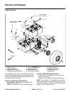
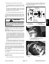
Removal (Fig. 51)
1. Park vehicle on a level surface, turn on/off switch
OFF, set parking brake and remove key from switch.
2. Remove cargo bed from vehicle (see Cargo Bed Re-
moval in Service and Repairs section of Chapter 5 –
Chassis).
3. Open the battery circuit by carefully removing one of
the battery cables (see Opening Battery Circuit in the
General Information section of this chapter).
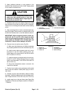
NOTE: Label all electrical leads for reassembly pur-
poses.
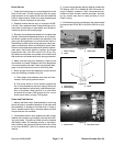
IMPORTANT: When removing wires from motor ter-
minals (A1, A2, F1 and F2), use a wrench to retain
lower nut while loosening upper nut (Fig. 53). If ter-
minal studs are allowed to turn during upper nut re-
moval, internal motor damage can occur.