


Workman e2050/e2065
Page 3 – 36
Electrical System (Rev. B)
3. Apply antiseize lubricant or axle grease to the
splines of the transaxle and motor shafts. Apply grease
to lip of seal in transaxle bore.
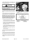
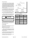
CAUTION
To prevent motor damage and personal injury,
make sure that traction motor is well sup-
ported as it is installed. Motor weighs approxi-
mately 62 pounds (28.1 kg).
4. Carefully lower motor into vehicle. Align motor shaft
with transaxle input shaft and slide motor to transaxle.
Take care to not damage thermal switch while installing
motor.
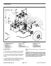
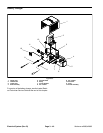
5. Align mounting holes of motor, transaxle and trans-
axle mount plate. Secure motor to transaxle with six (6)
socket head screws (item 1) and flat washers (item 2).
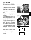
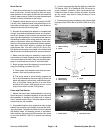
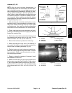
IMPORTANT: When connecting wires to motor ter-
minals (A1, A2, F1 and F2), use a wrench to retain
lower nut while tightening upper nut (Fig. 53). If ter-
minal studs are allowed to turn during upper nut
installation, internal motor damage can occur.
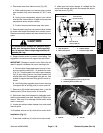
6. Connect wires to traction motor (Fig. 52):
A. Make sure that fasteners and cable connectors
are properly positioned on motor terminals (Fig. 56).
B. Install correct cable connector and nut to motor
terminals A1 and A2. While retaining lower nut,
torque upper nut on terminals A1 and A2 from 85 to
90 in–lb (9.6 to 10.2 N–m).
C. Install correct wire connector and nut to motor ter-
minals F1 and F2. While retaining lower nut, torque
upper nut on terminals F1 and F2 from 55 to 60 in–lb
(6.2 to 6.8 N–m).
D. Plug motor temperature sensor connector into
vehicle wire harness.
7. Position fan to traction motor and secure with socket
head screw and washer. Install plastic plug in hole in
rear frame.
8. Carefully connect removed battery cable to battery
terminals. Install lock washers and nuts on battery termi-
nals. Torque nuts from 115 to 125 in–lb (13 to 14.1 N–m).
9. Install cargo box to the rear frame (see Cargo Box
Installation in Service and Repairs section of Chapter 5
– Chassis).
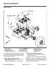
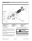
1. Transaxle
2. Screw/washer (6 used)
3. Transaxle mount plate
Figure 55
3
1
2
1. Upper nut
2. Cable connector
3. Lower nut
4. Flat washer
5. Insulating washer
6. Motor housing
Figure 56
3
4
1
2
5
6