


Workman e2050/e2065
Page 3 – 31
Electrical System (Rev. B)
Testing
When testing batteries in the Workman e2050 and
e2065, it is important to test all batteries. Proper perfor-
mance of the vehicle depends on all batteries being in
good condition. Testing will determine if one (or more) of
the batteries needs to be replaced.
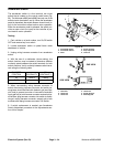
1. The preferred testing procedure is to use the Lester
Electrical 36/48 Volt Battery Discharge Unit (Model
17770). This instrument puts a known discharge load
(56.25 Amps) on the battery pack until the battery pack
reaches 42 volts. A timer incorporated into the discharg-
er measures the time needed to reach that voltage level.
Battery capacity and remaining life can be determined
from the test results. Refer to Discharge Unit Operating
Instructions for further information.
Other types of battery load testers can also be used to
test the Workman batteries. Many locally available bat-
tery load testers do not, however, have any adjustment
on the load that is put on the battery. Results received
from using load testers should follow the recommenda-
tions of the load tester manufacturer.
2. If the Lester Battery Discharge Unit (or other load
tester) is not available, an alternate battery test can be
done using a multimeter to perform a voltage test of
each battery. Use the following procedure:
A. For accurate voltage testing, allow batteries to re-
main idle (no charging, no discharging) for at least 6
hours and preferably 24 hours.
B. Open the battery circuit by carefully removing
one of the battery cables (see Opening Battery Cir-
cuit in the General Information section of this chap-
ter). Then, disconnect both cables from battery to be
tested.
C. Measure the battery voltage with the multimeter.
Record battery voltage. The measured voltage will
determine battery state of charge.
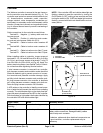
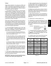
D. If voltage readings below 70% charged (see Fig.
47) exist, charge battery (see Operator’s Manual)
and take voltage measurements again. If voltage re-
mains low after charging, consider battery replace-
ment.
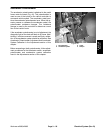
3. A third option for battery testing is to perform a specif-
ic gravity test of the battery electrolyte using a hydrome-
ter. Use the following procedure:
IMPORTANT: Make sure the area around the battery
fill caps is clean before removing the caps.
A. Remove battery filler caps. Do not add water prior
to testing specific gravity of battery electrolyte. If
electrolyte level is low, add distilled water and
charge battery (see Operator’s Manual) before per-
forming specific gravity test.
B. Measure the specific gravity of each cell with a
hydrometer. Fill and drain the hydrometer two to four
times before drawing a sample. At the same time,
take the temperature of the cell.
C. Have enough electrolyte in the hydrometer to
completely support the hydrometer float. Record the
hydrometer reading and return the electrolyte to the
battery cell.
D. Repeat test for remaining battery cells.
E. Temperature correct each cell reading. For each
10
o
F (5.5
o
C) above 80
o
F (26.7
o
C) add 0.004 to the
specific gravity reading. For each 10
o
F (5.5
o
C) below
80
o
F (26.7
o
C) subtract 0.004 from the specific grav-
ity reading.
Example: Cell Temperature 100
o
F
Cell Specific Gravity Reading 1.245
ADD (20
o
above 80
o
F) 0.008
Correction to 80
o
F 1.253
F. The specific gravity of all battery cells should be
1.277 +
.007. If low cell readings exist (see Fig. 47),
charge battery (see Operator’s Manual) and take
specific gravity readings again.
G. If specific gravity of any cells remain low after
complete charging, battery should be replaced.
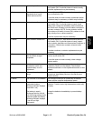
Battery Charge
Level
Specific
Gravity
Open Circuit
Voltage
100% 1.277 6.37
90% 1.258 6.31
80% 1.238 6.25
70% 1.217 6.19
60% 1.195 6.12
50% 1.172 6.05
40% 1.148 5.98
30% 1.124 5.91
20% 1.098 5.83
10% 1.073 5.75
Figure 47
Electrical
System