Workman e2050/e2065
Page 3 – 33
Electrical System (Rev. B)
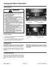
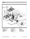
Traction Motor Brushes
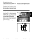
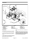
The traction motor in the Workman e2050/e2065 uses
eight (8) brushes. Traction motor brushes should be in-
spected every 500 hours of operation or annually.
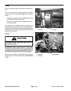
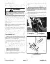
Inspection
1. Make sure that on/off switch is OFF. Raise and latch
bed to allow access to traction motor.
2. Open the battery circuit by carefully removing one of
the battery cables (see Opening Battery Circuit in the
General Information section of this chapter).
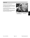
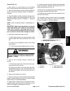
3. Unlatch headband of traction motor and reposition
headband to allow inspection of a brush at the top of the
motor.
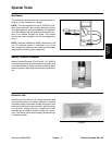
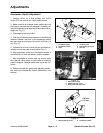
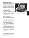
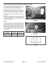
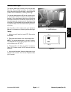
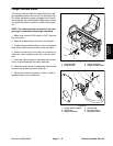
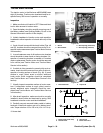
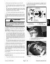
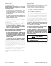
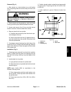
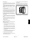
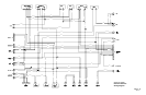
4. If end of brush is even with the brush holder (Figs. 48
and 50), brushes should be removed from motor for in-
spection and measurement (see Traction Motor Service
in this section).
5. In most instances, wear of all traction motor brushes
should be similar to wear found on the top brushes. If in-
spection of remaining brushes is needed or if brushes
require replacement, traction motor should be removed
from vehicle (see Traction Motor and Traction Motor
Service in this section).
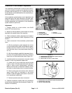
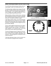
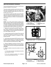
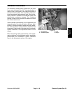
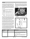
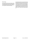
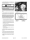
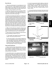
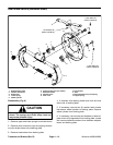
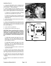
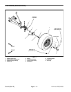
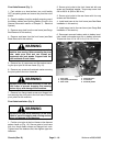
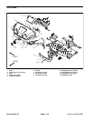
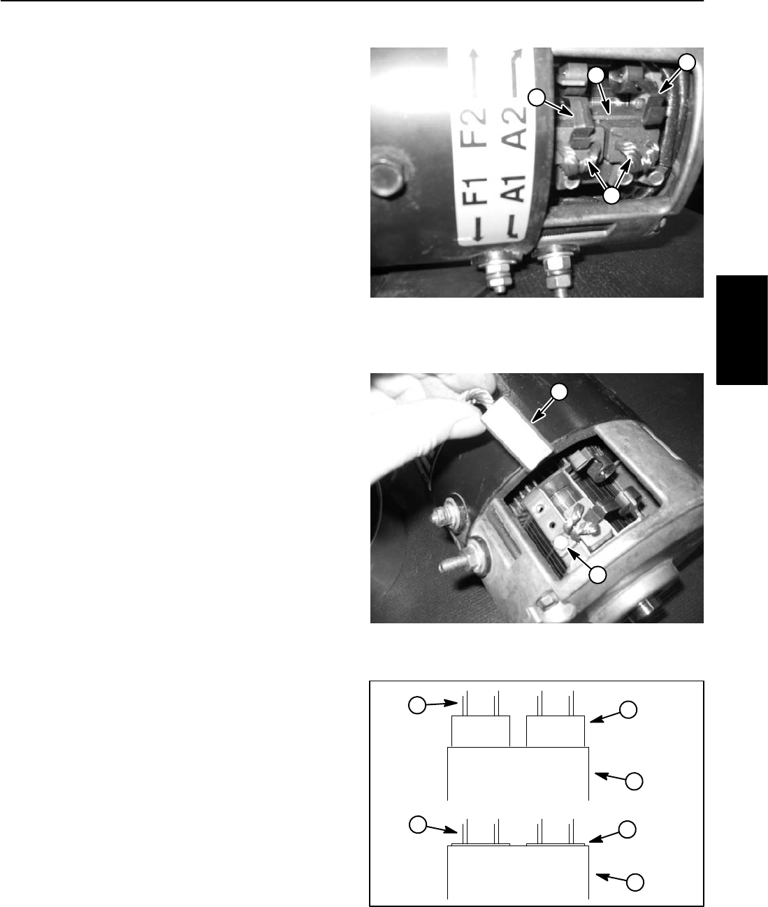
6. If vehicle is often operated in severely dirty environ-
ments, brush should be removed from motor to allow in-
spection of mating surface of brush (Fig. 49). If brush
surface is rough, pitted, arced or scored, additional
brush and/or motor inspection should be completed
(see Traction Motor and Traction Motor Service in this
section).
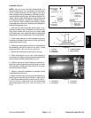
7. Visually inspect commutator surface of motor arma-
ture. If commutator surface is rough, pitted, arced or
scored, additional motor inspection should be com-
pleted (see Traction Motor and Traction Motor Service
in this section).
8. After brush inspection, make sure brush is correctly
installed in brush holder and tensioned by spring. Refit
headband to traction motor and latch headband.
9. Carefully connect removed battery cable to battery
terminals. Install lock washer and nut on battery termi-
nals. Torque nuts from 115 to 125 in–lb (13 to 14.1 N–m).
10.Lower bed.
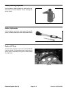
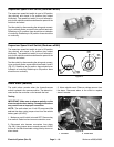
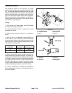
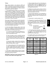
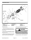
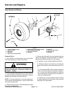
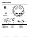
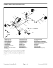
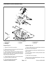
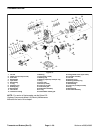
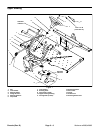
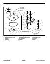
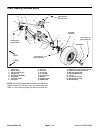
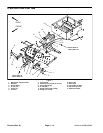
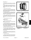
1. Brush
2. Brush holder
3. Brush spring (tensioned)
4. Brush spring (released)
Figure 48
2
1
3
4
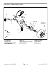
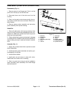
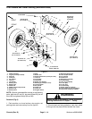
1. Removed brush 2. Cap screw
Figure 49
1
2
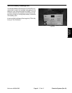
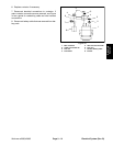
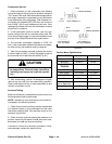
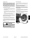
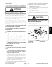
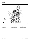
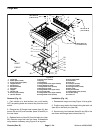
1. Brush holder (side view)
2. Normal brush
3. Worn brush
4. Brush shunt wire
Figure 50
1
3
1
2
4
4
Electrical
System