


Workman e2050/e2065 Page 5 – 15 Chassis (Rev. B)
3. Remove lug nuts and pull wheel assembly from ma-
chine.
4. Remove brake caliper from spindle (see Front Brake
Calipers in the Service and Repairs section of Chapter
4 – Transaxle and Brakes). Position caliper away from
wheel hub and spindle.
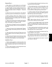
5. Carefully pry dust cap from wheel hub.
6. Remove cotter pin and nut retainer from spindle.
7. Remove jam nut that secures wheel hub to spindle.
Slide wheel hub with bearings and rotor from spindle.
8. Disassemble the wheel hub:
A. Pull the seal out of the wheel hub.
B. Remove bearings from both sides of the wheel
hub. Clean bearings in solvent. Make sure bearings
are in good operating condition. Clean the inside of
the wheel hub. Check the bearing cups for wear, pit-
ting or other noticeable damage. Replace worn or
damaged parts.
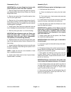
C. If necessary, remove four (4) socket head screws
and brake rotor from wheel hub.
9. Remove spindle:
A. Remove cotter pin and castle nut securing tie rod
ball joint to the spindle. Separate ball joint from the
spindle. Remove tie rod from Pitman arm if neces-
sary.
B. Remove lock nut and cap screw (19) securing the
spindle to the A–arm. Separate spindle from A–arm.
C. Locate and remove thrust washer from bottom of
kingpin sleeve in A–arm. Remove kingpin sleeve
from A–arm if necessary.
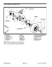
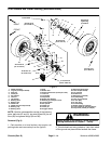
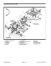
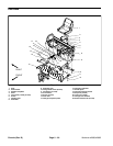
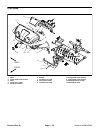
Installation (Fig. 6)
1. Install spindle as follows:
A. Position king pin sleeve into the pivot hub of the
A–arm. Sleeve must extend through the bottom of
the hub.
B. Place thrust washer onto the bottom of the king
pin sleeve. Then position spindle over the hub, king
pin sleeve and thrust washer.
NOTE: Make sure cap screw (19) is inserted down
through the spindle and A–arm hub.
C. Install brake hose bracket (20) onto cap screw
(19). Secure spindle to A–arm hub with cap screw
(19) and lock nut. Torque lock nut from 75 to 100 ft–lb
(102 to 136 N–m).
D. Insert tie rod ball joints down through the spindle
and up through the Pitman arm. Secure with castle
nuts.
E. Torque castle nuts from 20 to 25 ft–lb (27 to 34
N–m) to secure ball joint while aligning castle nut slot
with hole in ball joint stud. If necessary to align holes,
castle nut torque may be slightly more than specifi-
cation. Install cotter pin.
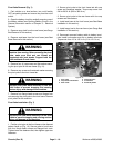
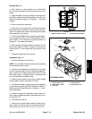
2. Assemble wheel hub:
A. If bearing cups were removed from the wheel
hub, press inner and outer cups into the hub until
they seat against the hub shoulder.
B. Pack both bearings with grease. Install inner
bearing into the cup on inboard side of the wheel hub.
IMPORTANT: The lip seal must be pressed in so it is
flush with the end of the hub. The lip of the seal must
be toward the bearing.
C. Apply grease to the inside of the new lip seal and
press it into the wheel hub.
D. If brake rotor was removed, apply Loctite #242 (or
equivalent) to socket head screws and install brake
rotor to hub. Make sure that the brake rotor bore
chamfer is assembled toward the wheel hub.
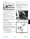
3. Slide wheel hub assembly onto spindle. Install outer
bearing, tab washer and jam nut onto spindle.
4. While rotating the wheel by hand, tighten the jam nut
from 75 to 100 in-lb (8.5 to 11.3 N–m) to set the bearings.
Then, loosen the nut until the hub has end play.
5. While rotating the wheel by hand, re-tighten the jam
nut from 15 to 20 in-lb (1.7 to 2.3 N–m).
6. Position nut retainer over jam nut and install cotter
pin through spindle shaft hole. Install dust cap to hub.
7. Install brake caliper to spindle (see Front Brake Cali-
pers in the Service and Repairs section of Chapter 4 –
Transaxle and Brakes).
8. Install wheel assembly with valve stem facing out.
Torque lug nuts from 45 to 65 ft–lb (61 to 88 N–m).
9. Lower machine to ground.
10.Align steering and toe–in (see Operator’s Manual).
11.Lubricate tie rod ball joints and king pin.
Chassis