


Workman e2050/e2065
Page 3 – 25
Electrical System (Rev. B)
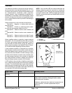
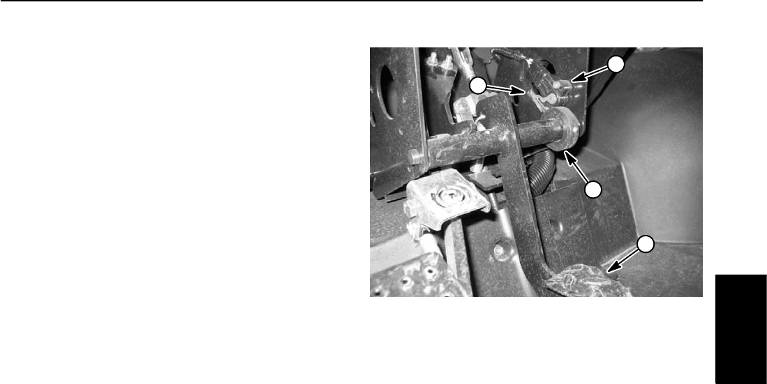
Accelerator Potentiometer
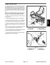
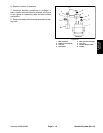
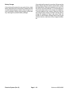
The accelerator potentiometer is attached to the pedal
frame under the dash (Fig. 40). This potentiometer is
used as one of the inputs for the vehicle controller to
command vehicle speed. The accelerator pedal posi-
tions the accelerator potentiometer lever. When the op-
erator presses or releases the accelerator pedal, the
potentiometer resistance changes. This resistance
change is used by the controller to determine current
flow to the traction motor.
If the accelerator potentiometer is out of adjustment, the
diagnostic light on the dash will flash six (6) times. Addi-
tionally, if vehicle movement is erratic and jerky, calibra-
tion of the accelerator system should be performed. See
Accelerator Potentiometer Adjustment and Accelerator
System Calibration in the Adjustments section of this
chapter.
Before suspecting a faulty potentiometer, follow adjust-
ment procedures for the accelerator switch, accelerator
potentiometer and acceleration system calibration
found in the Adjustments section of this chapter.
1. Potentiometer
2. Accelerator pedal
3. Collar
4. Roll pin
Figure 40
3
1
4
2
Electrical
System