


Workman e2050/e2065
Page 3 – 4
Electrical System (Rev. B)
Vehicle Operation
The Workman e2050 and e2065 electrical system use
a 48 volt battery pack, an electric traction motor, a ve-
hicle controller and numerous other electrical compo-
nents to allow vehicle operation.
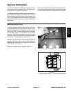
Eight, 6 volt, deep cycle batteries that are connected in
series provide current for a 48 volt DC, high torque trac-
tion motor, the vehicle controller and vehicle accesso-
ries (headlights, horn, various optional accessories).
The batteries are discharged as the vehicle is used so
charging the batteries after using the vehicle is neces-
sary. A battery discharge indicator gauge on the dash
provides the operator with information on battery charge
level. Demands on the vehicle during use (speed, pay-
load, incline use), battery condition (age, charge level),
ambient temperature and vehicle condition will all put
constraints on how long a vehicle can be used before the
batteries are discharged.
An automatic, 115 VAC (230 VAC on international mod-
els) battery charger is included with the vehicle. An inter-
lock switch on the vehicle charger receptacle prevents
the vehicle from operating when the charger cord is
plugged into the vehicle.
The electric traction motor directly drives a double re-
duction transaxle with differential. Operator inputs for
forward/reverse, supervisor switch position (high or low
speed) and accelerator pedal position are used by the
controller to determine voltage to the traction motor.
The traction motor is cooled with an external fan. Addi-
tionally, the motor is protected from overheating by a
thermal switch in the motor housing. If unsafe motor
temperature is sensed by the switch, the controller is
signaled to limit vehicle speed and torque until the motor
temperature reduces to a normal level.
The vehicle controller is a sealed electronic logic device
that uses inputs from several vehicle components to
control motor speed and direction. These inputs include
several switches (on/off, forward/reverse, accelerator,
supervisor, charger), a motor temperature sensor, an
accelerator pedal potentiometer and the vehicle contac-
tor (solenoid). The controller also provides regenerative
braking to assist in slowing the vehicle. The controller
has fault detection capabilities to help identify system
problems. Battery current is available to the controller
whenever the on/off switch is ON which energizes the
main contactor. A high current fuse protects this high
current circuit.
The Workman controller also provides a roll off warning
in instances when the vehicle begins to move (roll away)
after being stopped. On an incline and with the on/off
switch in the ON position, if the vehicle starts moving,
the alarm will sound warning the operator that the ve-
hicle is moving. When the vehicle goes into this roll–off
mode, regenerative braking will limit vehicle speed.
Vehicle accessories include headlights, horn and op-
tional electrical equipment. The accessories contactor
(solenoid) on the vehicle provides battery current to
these components when the on/off switch is ON. Fuses
provide circuit protection for these accessories.