


Workman e2050/e2065 Page 5 – 11 Chassis (Rev. B)
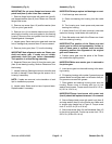
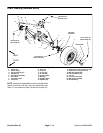
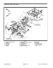
Removal (Fig. 3)
1. Park vehicle on a level surface, turn on/off switch
OFF, set parking brake and remove key from the on/off
switch.
WARNING
Before jacking up the machine, review and follow
Jacking Instructions in Operator’s Manual and
Chapter 1 – Safety.
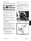
2. Chock wheels not being jacked up. Jack front wheel
off the ground and place blocks beneath the frame.
3. Loosen and remove five (5) lug nuts that secure
wheel to machine. Remove wheel from vehicle.
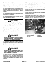
4. Remove wheel hub from spindle:
A. Carefully remove dust cap from the wheel to pre-
vent damage to the cap.
B. Remove cap screw and two (2) washers that se-
cure the wheel hub to the spindle. Slide wheel hub
from the spindle shaft.
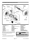
5. If necessary, remove bearings from both sides of the
wheel hub (Fig. 4). Discard removed bearings. Retrieve
spacer from wheel hub. Clean the spacer and the inside
of the wheel hub.
Installation (Fig. 3)
1. If bearings were removed from wheel hub, position
spacer in wheel hub and press new bearings into the
hub until the bearing retaining rings seat against hub
(Fig. 4).
2. Install wheel hub to spindle:
A. Apply antiseize lubricant to spindle shaft.
B. Slide wheel hub onto spindle shaft with the wheel
studs facing out.
NOTE: Apply Loctite #242 (or equivalent) to the
threads of the cap screw.
C. Place large washer and then small washer onto
the cap screw. Thread cap screw with washers into
the spindle shaft.
D. Torque cap screw from 135 to 165 ft–lb (183 to
224 N–m).
3. Position wheel to studs in wheel hub and secure with
five (5) lug nuts. Torque lug nuts from 45 to 65 ft–lb (61
to 88 N–m).
4. Lower machine to ground. Remove chocks from
wheels.
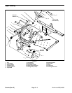
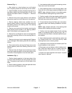
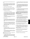
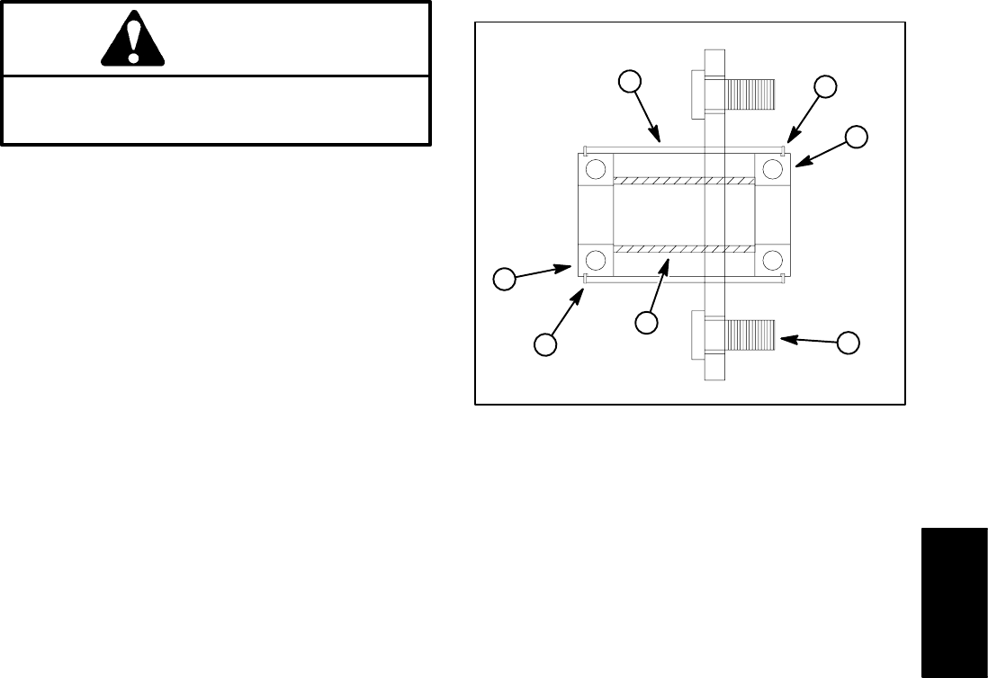
1. Wheel hub
2. Bearing
3. Retaining ring
4. Spacer
5. Wheel stud
Figure 4
2
3
1
2
3
4
5
Chassis