


Workman e2050/e2065
Page 3 – 22
Electrical System (Rev. B)
Fuses
There are three (3) fuses in the Workman electrical sys-
tem.
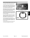
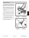
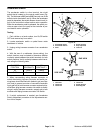
Two (2) of the fuses are located beneath the steering
column (Fig. 35). These fuses supply power to the fol-
lowing:
The upper 10 ampere fuse (F2) supplies power to the
on/off switch and switched circuits.
The lower 10 ampere fuse (F3) supplies power to op-
tional accessories.
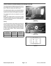
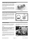
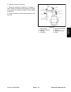
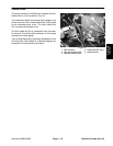
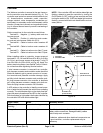
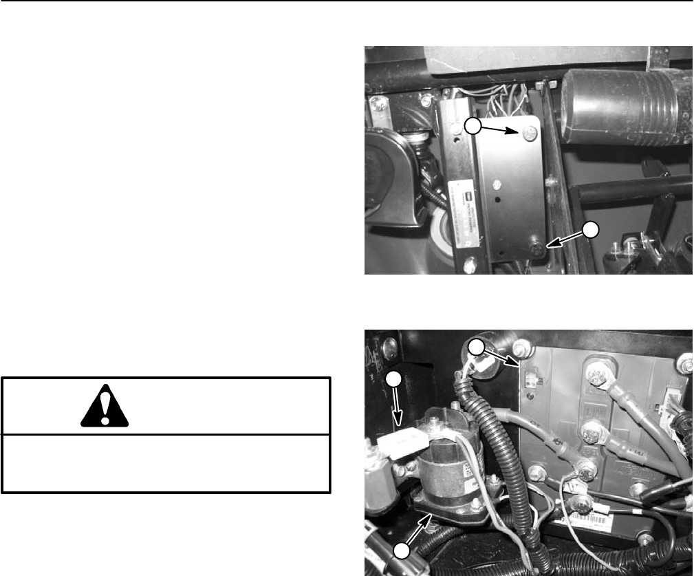
The third fuse (F1) is located under the controller cover
beneath the bed (Fig. 36). This fuse is rated at 355 am-
peres continuous and allows current flow between the
batteries and the vehicle. If this fuse has failed, vehicle
operation will not occur.
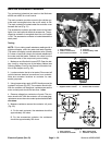
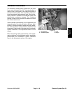
Testing
CAUTION
When testing fuses for continuity with a multime-
ter (ohms setting), make sure that fuse is re-
moved from circuit.
IMPORTANT: Before removing fuse F1 (355 Amp)
for testing, open the battery circuit by removing one
of the battery cables (see Opening Battery Circuit in
the General Information section of this chapter).
Make sure on/off switch is turned OFF. Remove fuse to
check continuity. The test meter should read less than
1 ohm.
Figure 35
1. Fuse (F2)
2. Fuse (F3)
2
1
1. Controller
2. Fuse (F1)
3. Main contactor
Figure 36
2
1
3