


Workman e2050/e2065
Page 3 – 18
Electrical System (Rev. B)
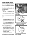
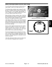
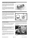
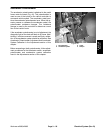
Supervisor Speed Limit Switch (Workman e2050)
The supervisor speed limit switch is open in Off position
(key vertical) and closed in On position (key rotated
clockwise). The speed limit switch is one of several in-
puts for the vehicle controller and allows the speed of the
vehicle to be limited.
Test the switch by disconnecting the wiring and connect-
ing a continuity tester across the two switch terminals.
Rotate key to On position: there should be an indication
of continuity. Rotate key to Off position: there should be
no continuity.
Figure 26
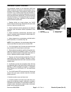
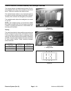
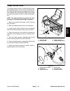
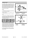
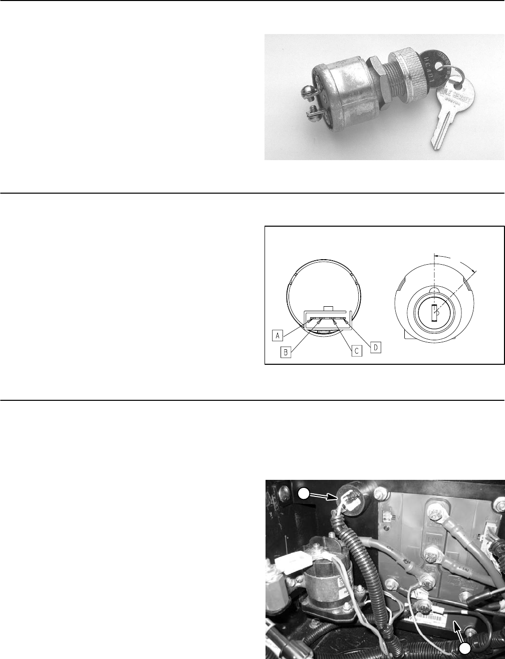
Supervisor Speed Limit Switch (Workman e2065)
The supervisor speed limit switch is open in Off position
(key vertical) and closed in On position (key rotated
clockwise). The speed limit switch is one of several in-
puts for the vehicle controller and allows the speed of the
vehicle to be limited.
Test the switch by disconnecting the wiring and connect-
ing a continuity tester across switch terminals A and D
(Fig. 27). Rotate key to On position: there should be an
indication of continuity. Rotate key to Off position: there
should be no continuity.
Figure 27
OFF
B&C
ON
B&C
A&D
45
o
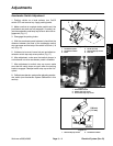
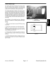
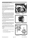
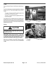
Audio Alarm (Reverse)
The audio alarm sounds when the forward/reverse
switch is placed in the reverse position. The alarm is lo-
cated under the controller cover beneath the bed.
Testing
IMPORTANT: Make sure to observe polarity on the
alarm terminals when testing. Damage to the alarm
may result from an improper connection.
NOTE: The audio alarm is a 12 volt DC component. Do
not test the alarm using jumper wires from the vehicle
battery pack (48 VDC).
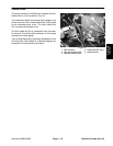
1. Make sure on/off switch is turned OFF. Remove key
from switch. Raise bed and remove controller cover.
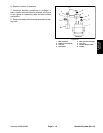
2. Disconnect wire harness connectors from alarm
(Fig. 28). Using jumper wires, correctly connect 12VDC
source to the alarm terminals noting polarity shown on
alarm decal.
3. Alarm should sound. Remove voltage source from
the alarm. Reconnect alarm to the circuit or replace
alarm if needed.
1. Controller 2. Audio alarm
Figure 28
2
1