


Workman e2050/e2065
Transaxle and Brakes (Rev. B)
Page 4 – 6
Adjustments
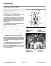
Adjust Brakes (Workman e2050)
The recommended brake pedal travel is from 1” to 1 1/2”
(25.4 to 38.1 mm) with a 75 to 100 pound (34 to 45.4 kg)
input force to the brake pedal.
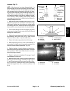
Adjustment Procedure (Figures 1 and 2)
1. Park vehicle on a level surface, turn on/off switch
OFF and remove key from the on/off switch.
2. Depress brake pedal lightly (10 to 15 pound input
force) until resistance is achieved. Check the gap be-
tween the brake lever and the brake lever stop to deter-
mine the distance the brake equalizer needs to be
adjusted (Fig 2).
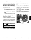
3. Remove the cotter pin and clevis pin that secure the
brake rod clevis to the brake lever.
4. Disconnect the spring from the hole near the end of
the brake rod.
5. Press the brake pedal down fully to raise the brake
lever away from the brake rod clevis.
6. Thread the brake rod in or out of the brake equalizer
as needed to remove the gap identified in Step 2. Do not
overtighten or brakes will drag and wear prematurely.
7. Reinstall the spring into the hole in the brake rod.
NOTE: Use a pry bar placed between the accelerator
pivot shaft and the brake equalizer to aid in installation
of the clevis pin that secures the brake rod clevis to the
brake lever.
8. Connect the brake rod clevis to the brake lever using
the clevis pin and cotter pin removed previously.
9. Verify that brake pedal travel is from 1” to 1 1/2” (25.4
to 38.1 mm) with a 75 to 100 pound (34 to 45.4 kg) input
force to the brake pedal.
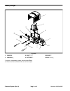
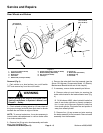
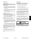
1. Clevis pin/cotter pin
2. Brake lever
3. Brake rod clevis
4. Brake rod
5. Brake equalizer
6. Spring
7. Brake cable
8. Accelerator pedal shaft
Figure 1
4
2
5
3
1
6
7
7
8
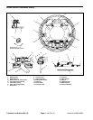
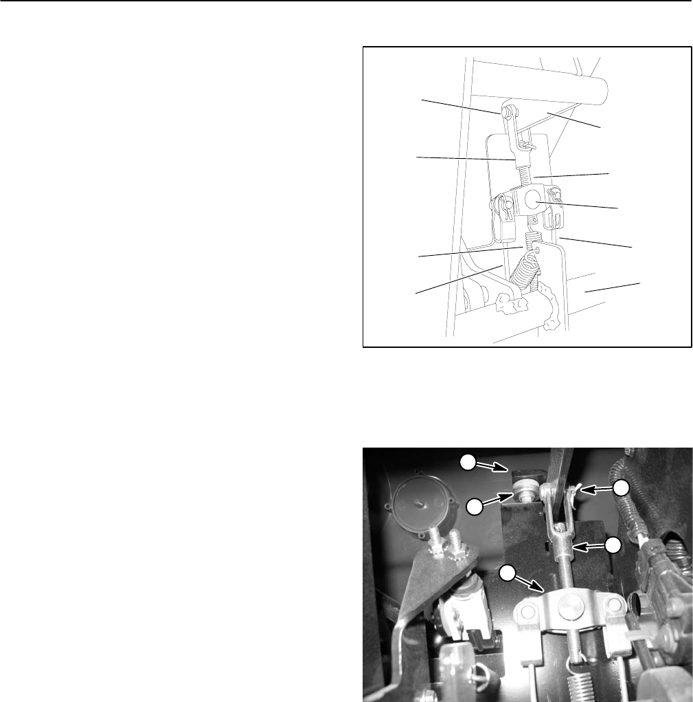
1. Brake lever
2. Brake lever stop
3. Clevis pin/cotter pin
4. Brake rod clevis
5. Brake equalizer
Figure 2
4
3
2
1
5