


Workman e2050/e2065
Page 3 – 38
Electrical System (Rev. B)
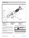
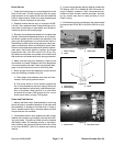
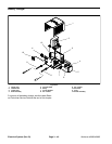
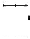
Traction Motor Service
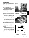
1. Frame and field assembly
2. Armature
3. Brush lead (2 used)
4. Cap screw (2 used per brush lead)
5. Cap screw (4 used)
6. Cap screw (8 used)
7. Brush (8 used)
8. High temperature sensor
9. Headband
10. Bolt (4 used)
11. Commutator end head
12. Bearing
13. Retaining ring
14. Brush spring (8 used)
15. Brush box
Figure 57
3
4
5
8
6
7
9
1
10
12
2
11
13
14
18 to 22 in–lb
(2 to 2.5 N–m)
120 to 140 in–lb
(13.6 to 15.8 N–m)
15
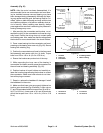
Disassembly (Fig. 57)
1. Unlatch and slide headband from traction motor.
2. Pull back the brush springs and latch them in the
open position on the spring holders. Slide brushes from
the brush holders.
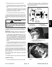
3. Use an arbor press or a bearing puller to remove the
armature from the commutator end head and frame and
field assembly (Fig. 58).
4. Remove four (4) bolts that secure the commutator
end head to the frame and field assembly. Remove com-
mutator end head from frame and field assembly.
5. Remove the retaining ring and press bearing from
the commutator end head. Discard the bearing.
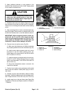
CAUTION
When using compressed air for cleaning motor
components, follow all safety instructions, in-
cluding wearing eye and respiratory protection.
6. Carefully blow out any accumulated carbon dust and
dirt from the commutator end head and the frame and
field assembly using clean, oil free, compressed air.