


Workman e2050/e2065 Page 5 – 23 Chassis (Rev. B)
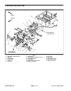
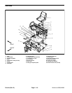
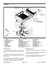
Removal (Fig. 14)
1. Park vehicle on a level surface, turn on/off switch
OFF, set parking brake and remove key from the on/off
switch.
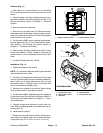
2. Open the battery circuit by carefully removing one of
the battery cables (see Opening Battery Circuit in the
General Information section of Chapter 3 – Electrical
System).
3. Remove screws attaching the wire harness connec-
tors to each headlight.
4. Remove two (2) cap screws (item 8) and flat washers
(item 7) that secure bumper to vehicle. Remove bumper.
5. Remove both flange head screws (item 11) securing
the center–lower hood to the front frame support.
6. Remove flange nut (item 4), both flat washers (item
9) and flange head screw (item 10) securing the hood to
each fender front.
7. Remove both flange nuts (item 4) and flange head
screws (item 2) securing the hood to the top of each
fender.
8. Remove two (2) flange head screws (item 2) secur-
ing the hood to the dash. Remove hood from the vehicle.
Installation (Fig. 14)
1. Position hood to the vehicle.
NOTE: Do not tighten fasteners securing the hood until
all fasteners are in place.
2. Install fasteners removed during hood removal:
A. Two (2) flange head screws (item 2) that fasten
hood to the dash.
B. Two (2) flange head screws (item 2) and flange
nuts (item 4) that fasten hood to the top of each fend-
er.
C. Flange head screw (item 10), two flat washers
(item 9) and flange nut (item 4) that fasten hood to
each fender front.
D. Two flange head screws (item 11) that fasten cen-
ter–lower hood to the front frame support.
3. Tighten all fasteners securing the hood.
4. Secure bumper to vehicle with two (2) cap screws
(item 8) and flat washers (item 7).
5. Connect wire harness connectors to headlight termi-
nals with screws.
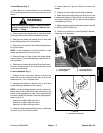
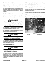
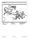
6. Reconnect removed battery cable to battery termi-
nals. Install lock washer and nut on battery terminals.
Torque nuts from 115 to 125 in–lb (13 to 14.1 N–m).
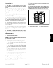
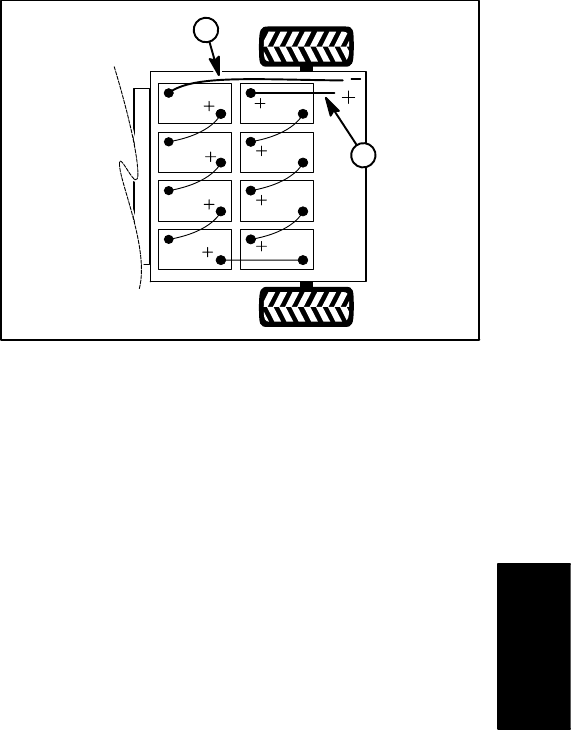
1. Negative cable to vehicle 2. Positive cable to vehicle
Figure 15
A
4
1
2
Chassis