


Workman e2050/e2065
Page 3 – 14
Electrical System (Rev. B)
Component Testing
For accurate resistance and/or continuity checks, elec-
trically disconnect the component being tested from the
circuit (e.g. disconnect the harness wire connectors
from the vehicle on/off switch before doing a continuity
check on the on/off switch).
CAUTION
When testing electrical components for continu-
ity with a multimeter (ohms setting), make sure
that power to the circuit has been disconnected.
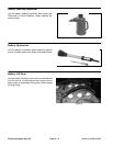
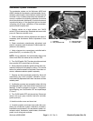
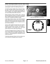
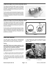
On/Off Switch
The Workman on/off switch is located on the dash panel
(Fig. 17). The switch has two (2) positions (OFF and ON)
and three (3) switch terminals. Only two of the terminals
are used on the Workman e2050 and e2065. The switch
terminals are positioned as shown in Figure 18.
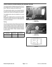
Testing
CAUTION
When testing the on/off switch for continuity
with a multimeter (ohms setting), make sure that
power to the circuit has been disconnected.
When the on/off switch is in the OFF position, no conti-
nuity should exist between the common (center) switch
terminal and the switched (side) terminal. In the ON
position, continuity should exist between the common
(center) switch terminal and the switched (side) termi-
nal.
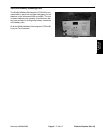
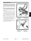
1. On/Off switch
Figure 17
1
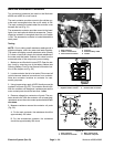
Figure 18
TERMINAL
COMMON
NOT USED
TERMINAL
SWITCHED
BACK OF
SWITCH