Rev. A
Workman e2050/e2065
Page 3 – 13
Electrical System (Rev. B)
Accelerator System Calibration
The accelerator system on the Workman e2050 and
e2065 includes the accelerator pedal assembly, the ac-
celerator potentiometer, the accelerator switch and the
controller. If any of these components are adjusted, re-
moved or replaced, the following calibration procedure
should be performed. Additionally, if vehicle movement
is erratic and jerky or if the diagnostic light on the dash
is flashing six (6) times, calibration of the accelerator
system should be performed.
1. Position vehicle on a level surface, turn On/Off
switch OFF and remove key. Raise bed and secure with
prop rod. Remove controller cover.
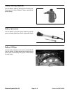
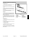
2. Check accelerator switch adjustment and adjust if
necessary (see Accelerator Switch Adjustment in this
section).
3. Check accelerator potentiometer adjustment and
adjust if necessary (see Accelerator Potentiometer Ad-
justment in this section).
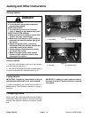
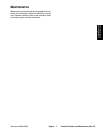
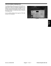
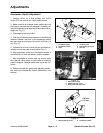
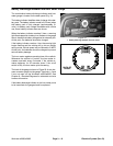
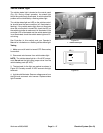
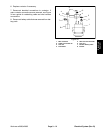
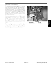
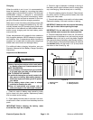
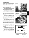
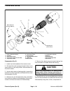
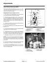
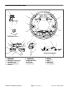
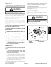
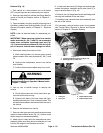
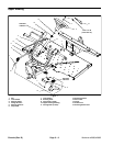
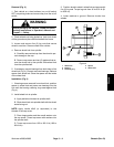
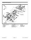
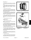
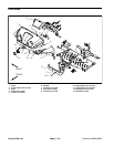
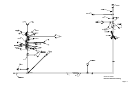
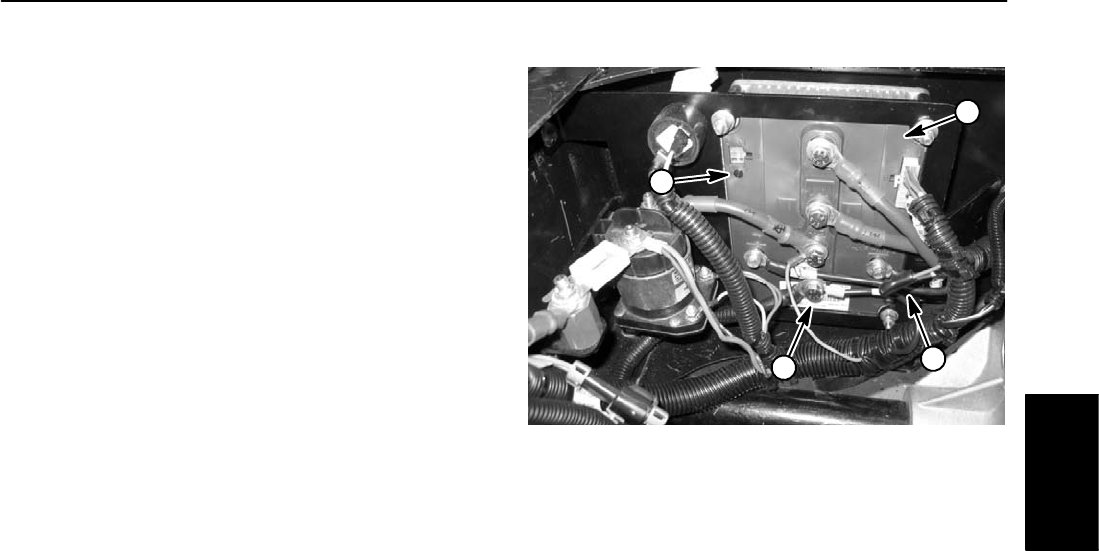
4. Using a jumper wire, connect gray controller lead to
ground post (B–) on controller (Fig. 16).
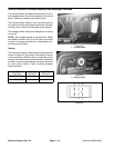
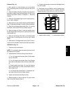
NOTE: During calibration, the vehicle status light on the
dash should flash the same as the controller LED.
5. Turn On/Off switch ON. The alarm should sound and
the controller LED should flash six (6) times.
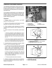
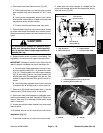
6. Slowly depress accelerator pedal until the alarm mo-
mentarily stops and hold pedal in position. This should
take a very small movement of the pedal. Once alarm re-
sumes, release accelerator pedal completely.
7. Depress and hold accelerator pedal fully. Alarm will
momentarily stop while controller calibration occurs.
Hold pedal fully depressed until alarm resumes and then
release pedal.
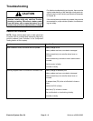
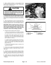
8. If calibration process was successful, alarm will chirp
and diagnostic light on the dash will be lit continuous (not
flashing). If alarm continues to sound or if diagnostic
light is flashing, turn On/Off switch OFF and repeat steps
5, 6 and 7.
9. Turn On/Off switch OFF and remove key. Disconnect
jumper wire from gray controller lead and controller
ground post (B–).
10.Install controller cover and lower bed.
11.If vehicle operation continues to be erratic after com-
pleting the accelerator system calibration procedure,
evaluate the components in the accelerator system: ac-
celerator switch, accelerator potentiometer, accelerator
pedal, circuit wiring and controller.
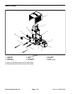
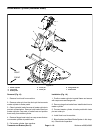
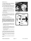
1. Controller
2. Gray controller lead
3. Ground post (B–)
4. Controller LED
Figure 16
2
1
3
4
Electrical
System