


Workman e2050/e2065 Page 5 – 17 Chassis (Rev. B)
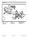
A–arm Removal (Fig. 7)
1. Park vehicle on a level surface, turn on/off switch
OFF, set parking brake and remove key from the on/off
switch.
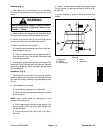
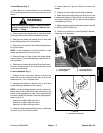
WARNING
Before jacking up the machine, review and follow
Jacking Instructions in Operator’s Manual and
Chapter 1 – Safety.
2. Chock wheels not being jacked up. Jack front wheel
off the ground and place blocks beneath the frame.
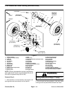
3. Remove front wheel and spindle from A–arm (see
Lower Steering Removal in this section).
4. Remove lock nut (item 6) and travel limiting bolt (item
9) from the frame.
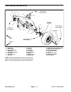
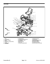
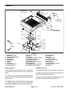
NOTE: To aid reassembly, note hole location of ride
height adjustment bolt in A–arm (Fig. 9).
5. Remove flange nut (item 5) and ride height adjust-
ment bolt (item 1) from the adjustment pattern of the A–
arm and frame.
6. Remove two centering bolts (item 8) and lock wash-
ers (item 7) securing the A–arm to the the frame. Lower
A–arm from the frame.
A–arm Installation (Fig. 7)
1. Position A–arm to the frame. Secure A–arm to the
frame with two (2) centering bolts (item 8) and lock
washers (item 7). Do not tighten bolts.
2. Install spindle and front wheel to the A–arm (see
Lower Steering Installation in this section).
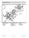
NOTE: If A–arm is being replaced, look for number be-
tween 200 and 400 written next to the serial tag on the
bottom of the replacement A–arm. This number should
be used to identify the location of the ride height adjust-
ment bolt (Fig. 9):
Number from 200 to 220 use hole 4.
Number from 225 to 285 use hole 3.
Number from 290 to 400 use hole 2.
3. Install ride height adjustment bolt (item 1) and flange
nut (item 5) into correct hole location.
4. Lower machine to ground. Remove chocks from
wheels.
5. Adjust front ride height (see Operator’s Manual).
6. Make sure that travel limiting bolt and lock nut are
installed and tightened. Tighten lock nut only enough to
snug travel limiting bolt. Do not deform frame plate by
overtightening lock nut.
7. Make sure that centering bolts are torqued from 240
to 290 ft–lb (325 to 393 N–m).
8. Check front wheel toe–in (see Operator’s Manual).
Adjust toe–in if necessary.
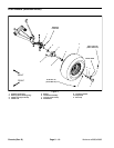
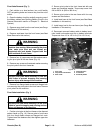
1. Travel limiting bolt
2. Centering bolt
3. A–arm (LH shown)
4. Ride height adj. bolt
Figure 8
240 to 290 ft–lb
(325 to 393 N–m)
2
3
4
2
1
1. Front A–arm (LH shown)
Figure 9
1
2
3
4
5
6
7
8
0
1
Chassis