


Workman e2050/e2065 Transaxle and Brakes (Rev. B)Page 4 – 11 (Rev. C)
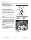
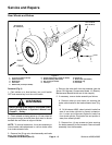
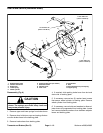
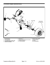
Disassembly (Fig. 5)
1. Remove auto adjust spring and shoe–to–shoe
springs from brake shoes.
2. Remove hold down pins and shoe cups securing the
brake shoes to the backing plate.
3. Remove brake shoes from backing plate.
Inspection
1. Inspect brake drums.
IMPORTANT:Brake drum machining is not recom-
mended. Replace brake drums as a set to maintain
equal braking forces.
A. Clean drums with denatured alcohol. Check
braking surface diameter in at least three places. If
the diameter exceeds 6.320 inches (16.05 cm), re-
place both brake drums.
B. Replace drums that are cracked, deeply grooved,
tapered, significantly out–of–round, scored, exces-
sively rusted or heat spotted.
C. Minor scoring can be removed with sandpaper.
2. Inspect brake shoe linings.
IMPORTANT:Replace brake shoes as a set (all four
shoes) to maintain equal braking forces.
A. Replace brake shoes if damaged or if lining is
worn to 1/16” (1.6 mm). Also, replace shoes if lining is
contaminated by oil, grease or other fluids.
NOTE: Overheated springs lose their tension and can
cause brake linings to wear out prematurely.
B. Inspect brake shoe webbing, shoe–to–shoe
springs and auto adjust spring for overheating. Over-
heating is indicated by a slight blue color. Inspect
brake shoe webbing for deformation. Replace parts
as necessary.
C. Inspect hold down pins and shoe cups for bends,
rust and corrosion. Replace as necessary.
3. Inspect backing plate surfaces which contact with
the brake shoes for grooves that may restrict shoe
movement. Replace backing plate if grooves can not be
removed by light sanding with emery cloth or other suit-
able abrasive. Replace backing plate if cracked, warped
or excessively rusted.
4. Inspect anchor abutment and rivets for deformation.
Replace entire brake assembly if deformation or exces-
sive rust is found.
5. Replace adjuster screw and shim washers if rusted,
corroded, bent or fatigued.
6. Replace brake cables if frayed, stretched or kinked.
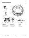
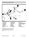
Assembly (Fig. 5)
IMPORTANT:Brake shoe lining surfaces must be
free of grease, oil and other foreign matter.
1. Apply a light film of lubricant to the following:
A. Surfaces of the shoe web that contact the back-
ing plate, push rod and adjusting screw.
B. Six ledges on which the brake shoes rest.
C. Entire surfaces of PTFE coated washers.
D. Entire surface of pivot pin.
E. Slot in push rod that contacts actuator lever.
F. Surfaces of adjusting lever that contact wave
washer, washer and pivot pin.
G. Surfaces of the actuator bracket that contact the
star wheel of the adjusting screw.
2. Position brake shoes to backing plate. Secure shoes
to plate with shoe cups and hold down pins.
3. Secure brake shoes with shoe–to–shoe springs and
auto adjust spring.
Transaxle and
Brakes