


Workman e2050/e2065
Transaxle and Brakes (Rev. B)
Page 4 – 8
Service and Repairs
Rear Wheels and Brakes
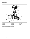
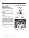
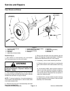
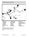
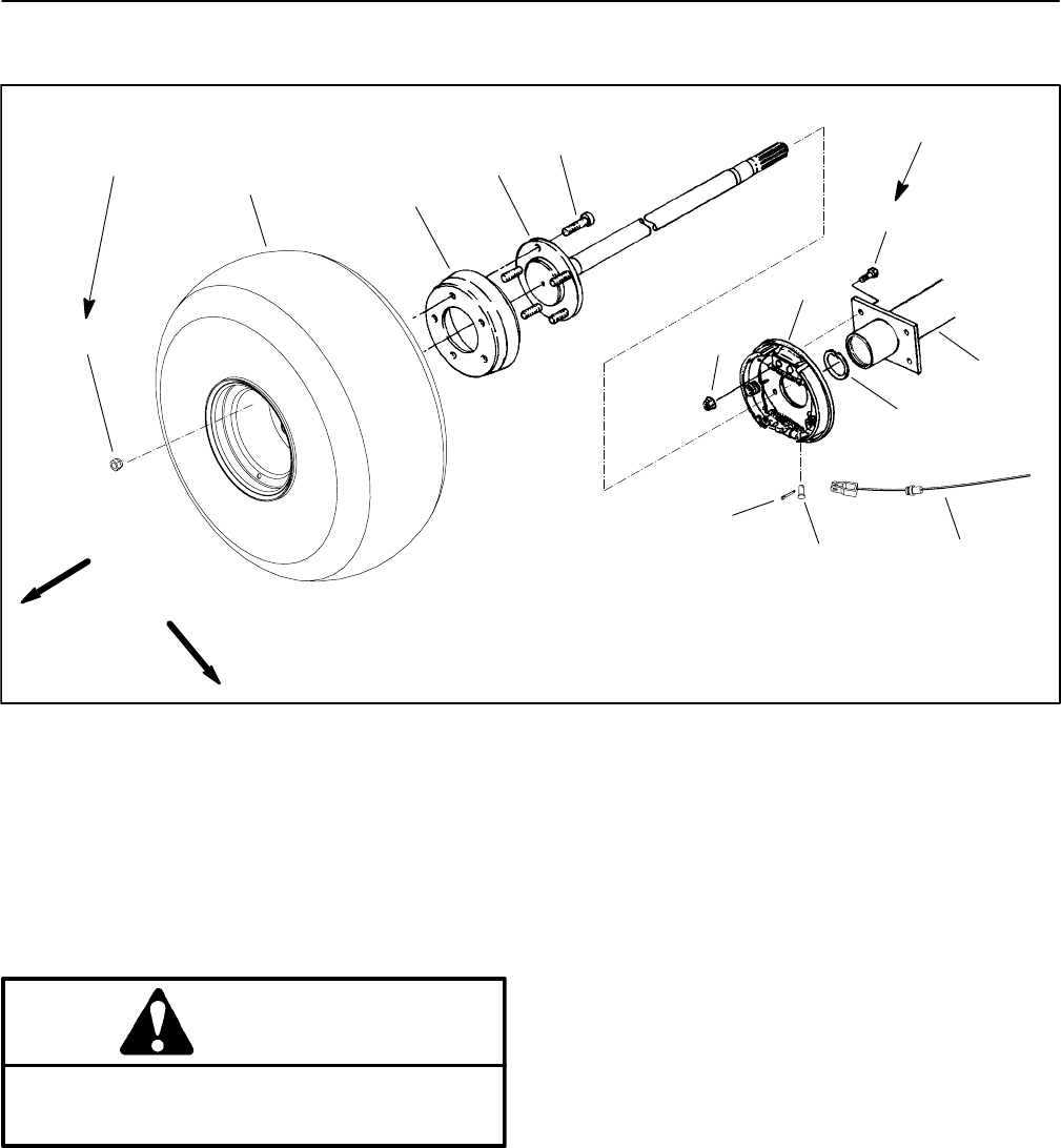
Figure 3
1. Lug nut (5 used per wheel)
2. Wheel assembly
3. Brake drum
4. Axle shaft
5. Wheel stud (5 used per wheel)
6. Flange head screw (4 used per brake)
7. Brake assembly (RH shown)
8. Nut (4 used per brake)
9. Cotter pin
10. Clevis pin
11. Brake cable (RH shown)
12. Retaining ring
13. Transaxle
13
45 to 65 ft–lb
(61 to 88 N–m)
FRONT
RIGHT
12
11
9
4
2
1
5
3
10
6
7
8
15 to 19 ft–lb
(20 to 26 N–m)
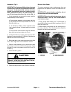
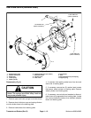
Removal (Fig. 3)
1. Park vehicle on a level surface, turn on/off switch
OFF and remove key from the on/off switch.
WARNING
Before jacking up the vehicle, review and follow
Jacking Instructions in Operator’s Manual and
Chapter 1 – Safety.
2. Chock wheels not being jacked up. Lift rear wheel off
the ground using a jack and place jack stand or blocks
beneath the rear frame to support vehicle.
NOTE: To remove brake drum, it may be necessary to
loosen brake cable adjustment or remove brake cable
from brake actuator lever.
3. Remove five (5) lug nuts, wheel assembly and brake
drum from the wheel hub.
4. Remove the axle shaft from the transaxle (see the
Spicer Off–Highway Components Model 12 (Electric)
Maintenance Manual at the end of this chapter).
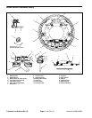
5. If necessary, remove brake assembly as follows:
A. Remove cotter pin and clevis pin securing the
brake cable bracket to the brake actuator lever (Fig.
4).
B. On Workman e2065, clean hydraulic brake line
area of rear brake cylinder to prevent contamina-
tion. Loosen and disconnect hydraulic brake line
from wheel cylinder. Plug brake line and position it
away from wheel cylinder.
C. Remove four (4) cap screws and nuts securing
the brake assembly to the transaxle. Remove brake
assembly from the transaxle.