


Reelmaster 4000–D
Page 4 – 55
Hydraulic System
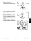
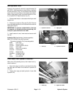
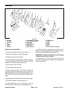
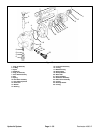
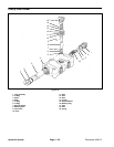
Disassembly of Steering Pump
1. Thoroughly clean outside of pump.
2. Use a sharp tool or marker to mark across front plate
(15), body (21) and back plate (22). This will assure
proper reassembly.
3. Clamp pump in a vise, with the shaft up.
4. Remove capscrews (11).
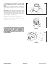
5. Remove pump from vise, hold pump in hands and
bump shaft against a wood block to separate front plate
(15) from back plate (22). Body (21) will remain with ei-
ther front plate or back plate.
6. If front plate (15) was removed first, remove wear
plate (20) from body gear pockets.
7. Remove drive gear assembly (7) and idler gear as-
sembly (10) from body (21).
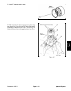
8. To separate body (21) from plate it remains with, put
drive gear assembly (7) in a bushing and tap protruding
end with a plastic hammer or soft mallet.
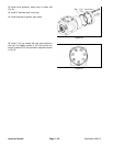
9. Remove O–ring (16) from front plate (15) and back
plate (22).
10. Remove backup–up gasket (19) from front plate
(15).
11. Remove bearing seal (18) from front plate (15) by
prying with a sharp tool.
12. Remove molded O–ring (17) from front plate (15) by
prying with a screwdriver.
13. Remove shaft seal (12) from front plate (15) by pry-
ing with a screwdriver.
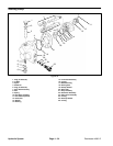
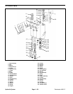
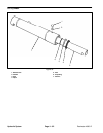
Disassembly of Back Plate Assembly (Flow Divider
/ Flow Control / Relief Valve)
1. Remove relief valve (23) from back plate (22).
NOTE: Do not disassemble relief valve cartridge as-
sembly – it must be replaced as an assembly.
2. Remove hex plugs (1, 6) flow divider spool (3), spring
(9) and disk (8).
Inspect Steering Pump Parts
GENERAL
1. Clean and dry all parts.
2. Remove all nicks and burrs from all parts with emery
cloth.
GEAR ASSEMBLY
1. Check drive shaft spline for twisted or broken teeth.
2. Inspect both drive gear (7) and idler gear (10) shafts
at bushing points and seal area for rough surfaces and
excessive wear.
3. If shaft measures less than 0.748” in bushing area,
the gear assembly should be replaced (one gear as-
sembly may be replaced separately; shafts and gears
are available as assemblies only).
4. Inspect gear face for scoring and excessive wear.
5. If gear width is less than 0.636”, the gear assembly
should be replaced.
6. Be sure snap rings are in grooves on either side of
drive and idler gears.
7. If edge of gear teeth are sharp, break edge with
emery cloth.
FRONT PLATE AND BACK PLATE
1. Oil groove in bushings in both front plate and back
plate should be in line with dowel pin holes and 1805
apart.
2. If I.D. of bushings in front plate (15) or back plate (22)
exceed 0.755”, front or back plate should be placed
(bushings are not available separately).
3. Bushings in front plate should be flush with face of
front plate.
4. Check for scoring on face of back plate. If wear ex-
ceeds 0.0015”, back plate should be replaced.
BODY
1. Check inside gear pockets for excessive scoring or
wear.
2. Body (21) should be replaced if I.D. of gear pocket ex-
ceeds 1.713”.
FLOW DIVIDER / FLOW CONTROL / RELIEF VALVE
1. Check disk (8) for wear.
2. Check spring (9) for weakness or breakage.
3. Wash back plate (22) in clean solvent, then direct
compressed air into relief valve and flow divider cavities
in back plate to remove any contamination.
Hydraulic
System