


Reelmaster 4000–D Page 7 – 9 Cutting Units
Hydraulic Motor Installation
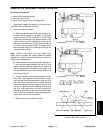
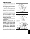
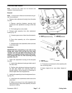
1. Install drive plate shield onto the reel drive motor
flange. Be sure the widest portion of the shield is at the
top (Fig. 13).
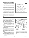
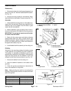
IMPORTANT:Make sure motor pulley set screws are
tight on the motor shaft before installing the motor
onto the cutting unit (Fig. 14).
2. Insert reel drive motor pulley through the housing,
and slip cutting unit drive belt over the pulley (Fig. 13).
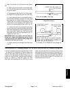
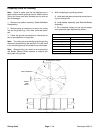
Note: Proper belt tension is achieved when the belt
deflects about 1/8 inch (3 mm) at the mid–point when 7
lb (31 N) of force is applied.
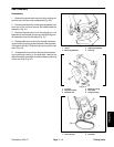
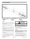
3. Insert two (2) reel drive motor mounting bolts (heads
on the inside of the drive housing with flat washer on the
top bolt through the reel motor flange holes. Thread
locknuts onto the bolts. Rotate reel motor upward in the
slotted hole in the housing to tension the drive belt.
Tighten fasteners to 25 ft–lbs (34 Nm). NOTE: (Fig. 15).
IMPORTANT:Rotate motors by hand only. Never
place a bar between hose fittings on the hydraulic
motors; motor damage may result.
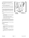
4. Install gasket and drive housing cover after making
sure the ends of the gasket are at the bottom of the hous-
ing to allow for drainage.
IMPORTANT:When hydraulic motors have been
mounted to the cutting units, make sure hydraulic
hoses lay flat and do not contact the frame of the
machine when the cutting units are in the raised
position. There should also be sufficient slack so
hoses are above and not in contact with the floata-
tion kit. If hoses appear twisted once the hydraulic
motors have been mounted and the belts tightened,
loosen swivel nuts at the motor and reposition
hoses. This can greatly increase the life of the
hoses. With cutting units down, all cutting unit
hoses should have a flat natural lay and be free from
twist.
Note: Refer to the Traction Unit Operator’s Manual for
instructions on setting the adjustable hydraulic counter-
balance.
1. Drive plate shield 2. Reel drive motor flange
Figure 13
1. Hydraulic motor
2. Motor pulley
3. Drive belt
Figure 14
1. Mounting bolts 2. Drive housing
Figure 15
2
Cutting Units