


Reelmaster 4000–D
Page 3 – 16
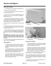
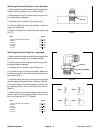
Kubota Diesel Engine
Engine Installation
CAUTION
One person should operate lift or hoist while the
other person guides the engine into the frame.
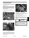
1. Install engine to the front engine mounts and rear
brackets.
A. Attach a hoist or lift to the engine.
IMPORTANT: Make sure not to damage the engine,
fuel and hydraulic lines, electrical harness, or other
parts while installing the engine.
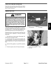
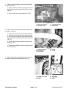
B. Place gasket onto exhaust bracket to receive ex-
haust tube (Fig. 26).
C. Lower engine slowly into the machine.
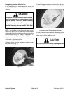
2. Secure both front brackets to the engine mounts
with cap screw, flat washers, spring washer, and hex nu.
Torque cap screw and hex nut from 59 to 73 ft–lb (8.2 to
10.1 kg–m)t (Fig. 26).
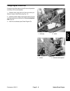
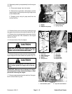
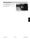
3. Secure engine to the spacers and rear brackets with
three cap screws and lock washers. Torque cap screws
from 61 to 75 ft–lb (8.4 to 10.4 kg–m) (Fig. 27).
4. Secure exhaust tube and gasket to the exhaust
bracket with three cap screws and lock nuts (Fig. 26).
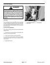
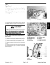
5. Connect hydraulic pump assembly to the engine
(Fig. 25).
A. Position the pump shaft into the spring coupling.
B. Secure pump mounting flange to the pump
adapter plate with four cap screws, flat washers,
and lock washers. Torque cap screws from 60 to 80
ft–lb (8.3 to 11.1 kg–m).
C. Connect damper to the bracket.
6. Connect throttle control cable to the swivel lever.
Secure cable to engine plate with R–clamp (Fig. 24).
7. Connect wire harness and electrical wires to the en-
gine as follows:
A. Connect wire and connector to the alternator,
red cable to starter, three wires to the starter, wire to
the oil pressure switch, and wires to high tempera-
ture warning and shutdown switches (Fig. 20).
B. Connect electrical connector to the fuel solenoid
(Fig. 22).
C. Connect red/black wire to the glow plug bus bar
(Fig. 23).
8. Connect the following fuel hoses:
A. Suction hose at the injector pump from the fuel
filter. Suction and discharge hoses at the fuel pump
(Fig. 22).
B. Return hose from the fuel injectors (Fig. 23).
C. Remove clamps used to prevent drainage.
9. Position fan shroud to the radiator. Install fan to the
fan pulley (Fig. 21).
A. Apply Loctite (Blue) 242 or equivalent to the
ends of the cap screws.
B. Torque cap screws from 80 to 110 in–lb (92 to
127 kg–cm).
10. Install fan shroud and guard to the radiator (Fig. 20).
11. Install exhaust shield to the engine (Fig. 20).
12. Install air hose to air intake manifold (Fig. 20).
13. Install battery the machine and connect cables (see
Battery Service in Chapter 5 – Electrical Systems).
14. Connect both hoses to the radiator (Fig. 20).
15. Secure canopy to the brackets (Fig. 19).
16. Fill radiator with coolant (see Check Cooling Sys-
tem).
17. Adjust control cable throttle cable (Fig. 24).
A. Push throttle lever to the FAST position.
B. Loosen screw on swivel that secures the cable to
the swivel lever.
C. Adjust position of swivel lever with cable so the
injector pump lever is contacting the stop in the full
throttle position.
D. Secure cable to swivel with screw.
18. Prime fuel system (see Prime Fuel System).
19. Check traction pedal adjustment for NEUTRAL.