


Reelmaster 4000–D
Page 4 – 65
Hydraulic System
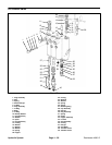
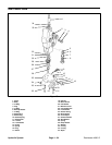
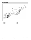
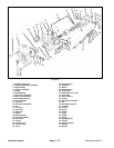
Disassembly of Reel Control Valve Assembly
1. Plug all outlets and thoroughly clean outside of valve.
2. Remove plug (4) and O–ring (3).
3. Remove relief valve components (8, 7, 6, & 5).
4. Remove screws (22) and lock washers (23).
5. Remove detent block (25).
6. Remove detent plug (9), spring (10), and pawls (11)
from detent block (25).
7. Remove screw spool (26).
8. Remove shallow washer (27), wire washer (28),
spring (29), deep washer (30), washer (31), and O–ring
(32).
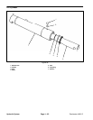
9. Remove spool (1).
10. Remove all O–rings and back–up washers from all
plugs, relief valves, and body bore.
11. Thoroughly clean all parts.
Inspection of Reel Control Valve Assembly
1. Remove nicks and burrs from all parts.
2. Inspect spool and body bore for excessive wear.
NOTE: If internal leakage with the spools in spring–
centered position has been experienced, wear is indi-
cated between the spool and body bore. This can be
corrected by replacing the spool and body as an as-
sembly. Spools or bodies cannot be serviced separately.
3. Inspect relief valve.
NOTE: The pilot–operated cartridge–type relief valve is
not adjustable and is pre–set at the factory. However, to
ensure cleanliness in the system; snap ring, washer,
and screens may be removed, cleaned with air, and re-
placed.
4. Inspection of O–rings and back–up washers is not ne-
cessary. It is recommended that these be replaced as
new parts.
5. Inspect seats in body for wear.
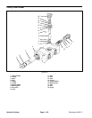
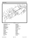
Reassembly of Reel Control Valve Assembly
1. Thoroughly clean and dry all parts. Metal parts should
be lightly oiled prior to assembly.
NOTE: All O–rings and back–up washers should be re-
placed as new parts.
2. Position O–rings (5, 32, & 33) in body bore.
3. Install O–rings and back–up washers on relief valve
and plugs.
4. Install plug (4).
5. Install O–ring (32), washer (31), deep washer (30),
spring (29), wire washer (28), and shallow washer (27)
into proper position in body casting.
6. Insert spool (1) into body bore and screw spool screw
(26) into spool.
7. Install spring (10), pawls (11), spring (10) and detent
plug (9) into detent block (25).
8. Slip detent block (25) over spool screw (26) and se-
cure to valve body (2) with lock washers (23) and cap
screws (22).
9. Install relief valve (8).
10. Run operational check.
Hydraulic
System