


Reelmaster 4000–D Page 5 – 21 Electrical System (Rev. A)
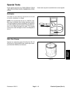
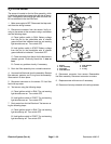
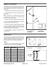
Fuel Sender
The sender is located on top of the fuel tank under the
rear screen.
1. Remove gray wire and black ground wire from the
sender.
2. Remove truss head screws and lock washers from
the sender and fuel tank.
3. Remove sender and gasket from the fuel tank.
Clean any fuel from the sender.
Note: Before taking small resistance readings with a
digital multimeter, short test leads together. The meter
will display a small resistance value. This internal resis-
tance of the meter and test leads should be subtract
from the measured value of the component.
CAUTION
Make sure sending unit is completely dry (no fuel
on it) before testing. Perform test away from the
tank to prevent an explosion or fire from sparks.
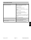
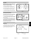
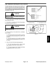
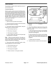
4. Check resistance of the sender with a multimeter.
Resistance with the float in the full position should be
27.5 to 39.5 ohms. Resistance with the float in the empty
position should be 240 to 260 ohms.
5. Replace sender as necessary. Reinstall sender into
fuel tank. Connect wires.
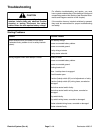
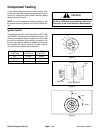
1. Truss head screw
2. Lock washer
3. Fuel sender
4. Gasket
5. Fuel tank
Figure 12
1
2
3
4
5
Figure 13
1. Full position 2. Empty position
1
2
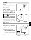
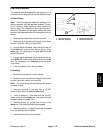
Fuel Gauge
The fuel gauge can be tested using a new gauge as a
substitute or by the use of a DC voltage source and a
variable resistance box.
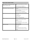
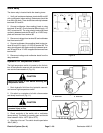
1. Connect the fuel gauge to the variable resistance
and DC voltage source (Fig. 14).
2. Adjust resistance until the gauge needle points to
following test points on the gauge (Fig. 14):
A. The left edge of the red area (empty); the resis-
tance setting should be from 238 to 242 ohms.
B. The right edge of the green area (full); the resis-
tance setting should be from 28 to 38 ohms.
3. Disconnect the voltage source, gauge, and variable
resistance.
Figure 14
+
–
VARIABLE
RESISTANCE
14 VDC
1. Empty position 2. Full position
1
2
Electrical
System