


Reelmaster 4000–D
Page 4 – 40
Hydraulic System
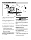
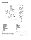
Steering Control Unit
1
2
3
4
5
6
7
8
9
10
16
18
19
20
21
22
23
24
25
26
27
28
11
12
13
14
15
12
12
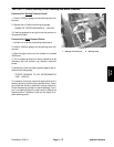
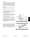
Figure 25
1. Seal 1” I.D.
2. Retaining Ring
3. Seal Gland Bushing
4. Seal 1.875 I.D.
5. Quad Ring Seal, 1.062 I.D.
6. Bearing Race
7. Thrust Bearing, Needle
8. Housing
9. Control Sleeve
10. Centering Spring Kit
11. Control Spool
12. Seal
13. Spacer Plate
14. Drive
15. Gerotor
16. End Cap
18. Cap Screw
19. Pin Kit, Centering
20. Spring
21. Retainer Plug
22. Check Ball
23. Check Ball, Retainer
24. Check Ball
25. Seal
26. Check Ball Seat
27. Seal
28. Set Screw
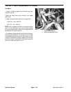
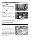
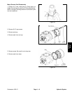
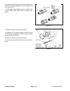
Disassembly
Cleanliness is extremely important when repairing a
steering control unit. Work in a clean area. Before dis-
connecting lines, clean port area of unit thoroughly. Use
a wire brush to remove foreign material and debris from
around exterior joints of the unit.
NOTE: Troubleshooting information defines terms and
problems, possible causes for problems, and recom-
mends procedures for correcting problems.
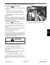
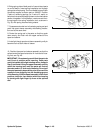
Although not all drawings show the unit in a vise, we rec-
ommend that you keep the unit in the vise during disas-
sembly. Follow the clamping procedure explained
throughout the manual.