


Reelmaster 4000–DPage 7 – 12Cutting Units
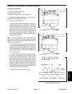
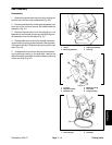
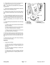
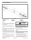
6. Disassemble cover from the drive housing and re-
move the drive belt from the housing (Fig. 23).
Note: Reel capscrew is assembled with a thread lock-
ing compound
7. Remove reel capscrew, toothed washer, and pulley
washer from the reel shaft (Fig. 23).
8. Remove driven pulley from the reel shaft using a
puller. Remove woodruff key from the reel shaft (Fig.
23).
9. Remove adjustment assembly and cone nut, belle-
ville washer, and shoulder bolt securing the drive hous-
ing to the side plate. Remove drive housing (Fig. 23).
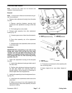
10. Slide reel assembly out of the slots in the side
plates.
11. Inspect bearings and grease seals in their housings
as follows:
A. Seals must be free of cracks and tears. Replace
seals as necessary.
B. Bearing roller balls must be free of deformation
and scoring. Replace bearing if necessary.
C. Bearing must spin freely and have minimal axial
play. Replace bearing if necessary.
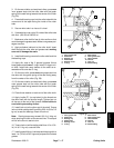
12. Remove retaining ring from inside the drive hous-
ing. Pry outer seal out of the belt drive case side. Press
bearing and rear seal out from the outer side of the hous-
ing.
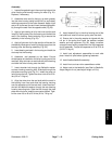
13. Remove the dust cap (Fig. 20). Press the bearing
and seal out of the housing.
Inspection
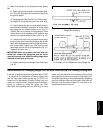
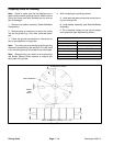
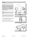
1. Inspect reel as follows:
A. Check reel shaft for bending and distortion by
placing the shaft ends in V–blocks. Replace reel if
necessary.
B. Check reel blades for bending or cracking. Re-
place reel if necessary.
C. Check service limit of reel diameter (see Reel
Grinding Specifications in Preparing Reel for Grind-
ing).
1. Cap screw
2. Pulley washer
3. Driven pulley
4. Drive housing
5. Adjustment handle
6. Woodruff key
7. Drive housing fasteners
Figure 23