


Reelmaster 4000–D
Page 4 – 52
Hydraulic System
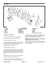
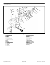
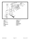
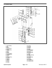
Reel Motor
2
3
4
5
6
7
8
9
10
11
12
13
14
5
7
20
19
18
16
17
15
21
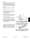
1. Not used
2. Idler Gear
3. Drive Gear
4. Key
5. O–Ring
6. Body
7. Dowel Pin
8. Plate & Bushing Assembly
9. Socket Head Cap Screw
10. Set Screw
11. Drive Pulley
12. Retaining Ring
13. Shaft Seal
14. Backup Washer
15. Relief Valve Kit
16. O–Ring
17. Plug
18. Shim
19. Spring
20. Ball
21. Back Plate/Relief Assembly
Figure 54
Disassembly of Reel Motor
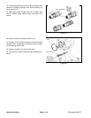
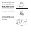
1. Remove set screws (10) from drive pulley (11).
2. Remove drive pulley (11) from drive shaft.
3. Remove key (4) from drive shaft.
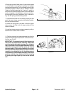
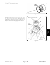
4. Clean outside of motor thoroughly. Scribe a line along
front plate assembly (8), body (6), and back plate as-
sembly (21) to assure proper reassembly.
5. Clamp motor in vise, shaft up.
6. Remove eight cap screws (9).
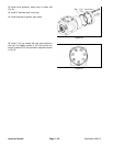
7. Remove motor from vise, hold motor in hands and
bump shaft against wooden block to separate the front
plate assembly (8) from the back plate assembly (21).
The body (6) will remain with either the front or back
plate.
8. Separate body (6) from either the front or back plate.
9. Remove drive gear (3) and idler gear (2).
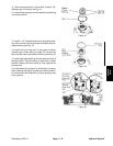
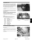
10. Remove retaining ring (12), shaft seal (13), and
back–up washer (14) from front plate assembly (8).
11. Remove the two O–rings (5) and two dowel pins (7)
between front plate assembly (8) and body (6), and be-
tween body (6) and back plate assembly (21).
IMPORTANT: Remove relief valve kit only if testing
indicates the relief valve is faulty.
12. Remove plug (17) and O–ring (16) from the back
plate (21). Remove shim (18), spring (19), and ball (20)
from the back plate.