


Reelmaster 4000–D
Page 4 – 75
Hydraulic System
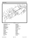
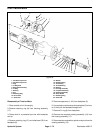
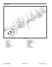
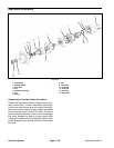
IMPORTANT: Do not attempt to disassemble the
piston block and spring. The parts are not service-
able separately. The rotating assembly (19) must be
replaced as an assembly.
10. Remove camplate assembly (18) from housing.
11. Remove shaft seal (11) from housing.
12. Remove washer (12) and drive shaft (10) from hous-
ing.
13. Remove the two retaining rings (13), thrust races
(14), and thrust bearing (15) from drive shaft (10).
Inspection of Traction Motor
1. Wash all parts thoroughly in a suitable solvent.
2. Examine bearings (16) and (7) in housing (17) and
backplate (5). If the needles are free of excessive play
and remain in the bearing cage, there is not need to re-
place the bearing.
3. Inspect thrust races (14) and thrust bearing (15). All
surfaces should be free of any signs of wear or fretting.
4. Inspect spider and pivot; conical surfaces should be
free of wear and score marks.
5. Inspect the pistons; the O.D. surface should be
smooth and free of scoring. The shoes should be snug
fit to the piston. The face of the shoes should be flat and
free of scoring and flaking. Do not lap piston shoes.
6. Inspect the piston block; the bores should be free of
scoring. The surface that contacts the backplate should
be smooth and free of grooves or metal build–up.
7. Inspect the camplate assembly (18); the surface op-
posite the chamfered side should show no signs of scor-
ing.
8. Inspect the flat surface on the backplate (5); it should
be free of excessive scoring or metal build–up.
9. Inspect the drive shaft (10) for fretting in the bearing
areas. Check spline area for twisted or broken teeth. If
keyed shaft, check for cracked or chipped keyway.
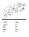
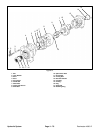
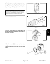
Reassembly of Traction Motor
1. Lubricate all critical moving parts before assembly.
2. Install one retaining ring (13) in rear groove on drive
shaft (10). Install one thrust race (14), thrust bearing
(15), and second thrust race (14) on drive shaft (10).
Install second retaining ring (13) in front groove on drive
shaft.
3. Replace needle bearing (16) in housing (17) if neces-
sary. Install shaft in housing assembly (17). Install wash-
er (12), shaft seal (11) and retain with retaining ring (9).
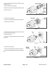
4. Install the pivot, spider, and the piston assemblies in
the piston block assembly.
5. Lubricate camplate assembly (18) and install in hous-
ing assembly with chamfered edge of race against
housing surface.
6. Install piston block assembly in housing assembly.
The piston shoes must contact the camplate assembly
(18). Be sure all parts are in their proper position.
7. Install new bearing (7) in backplate (5) if necessary.
8. Install new O–ring (6) on backplate.
9. Install backplate (5) on housing.
10. Install capscrew (1 & 2) and torque 15–18 ft. lbs.
Hydraulic
System