


Reelmaster 4000–D
Page 4 – 73
Hydraulic System
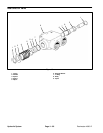
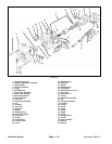
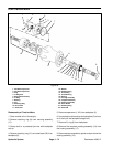
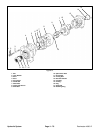
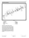
Reassembly of Traction Pump
1. Clean all parts in suitable solvent, lubricate all critical
moving parts before reassembly. If necessary, install
new needle bearings in the housing. The camplate pivot
bearings are slip fit; the needle bearing (6) is press fit,
install with numbered end of the bearing outward.
2. Insert camplate into housing. Insert the needle bear-
ings (18) over the arm and slide into the housing.
3. Install washers (17) and shaft seal (16) over cam piv-
ot bearing. Install seal cover (15) and secure with
screws (24).
4. On the opposite side of housing install needle bearing
(18), inner race (20) with chambered I.D. inward, wash-
er (17), O–ring (21), and O–ring cover (22), and secure
with trunnion cover (23) and screws (24).
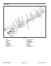
5. Install retaining ring (28) on drive shaft (31). Install
thrust race (29), thrust bearing (30), and second thrust
race (29), secure with second retaining ring (28).
6. Install shaft in housing and install washer (27), shaft
seal (26), and retain with retaining ring (25).
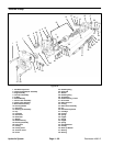
7. Install the pivot, spider and the piston assemblies in
the piston block. Install rotating assembly in the housing
assembly, the piston shoes must be in contact with the
camplate.
8. Clamp pump assembly in a protected jaw vise with
the open end of the housing up.
9. Install new housing gasket (10).
10. Install back plate (9).
11. Install ball and pin into check valve housing if remo-
ved. Install new O–ring (45) and back–up washer (46)
on check valve assembly (8). Install O–ring nearest pin.
Install in back plate (9) with pin in back plate.
12. Install key (35) on shaft and install gerotor gear (7)
over shaft.
13. Install new O–ring (5) in groove in charge pump
adaptor (2), hold in place with clean clear grease. As-
semble adaptor on pump back plate. Retain with four
cap screws (36 & 1) and torque to 27/31 ft. lbs.
14. Reassemble tow valve assembly (4) by installing
new O–rings, inserting spreader into separators plug,
and securing with retaining ring.
15. Install tow valve assembly (4) in back plate (9) and
torque 27 to 30 ft. lbs.
16. Install relief valve assemblies (34) in back plate.
17. Install new O–ring (33) and spring (41) on plug (3).
Install plugs (3) in back plate and torque 55/60 ft. lbs.
18. Remove pump from vise and install poppet (42),
spring (43), and spring retainer (44).
Hydraulic
System