


Reelmaster 4000–D
Page 4 – 38
Hydraulic System
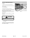
TEST NO. 8: Check Lift Circuit Working and Relief Pressure
Procedure For Working Pressure Check:
1. Install a 5,000 psi gauge onto the quick disconnect of
the lift valve.
2. Operate the unit while monitoring the gauge. Gauge
should read from 500 to 2900 PSI.
3. If working pressure is too high or too low, perform re-
lief pressure check.
Procedure For Relief
Pressure Check:
1. Hydraulic oil must be at operating temperature.
2. Install a 5,000 psi gauge onto the quick disconnect of
the lift valve.
3. Start the engine and move the throttle to full speed
(2500 rpm).
4. Engage the control lever into the “LIFT” position. Mo-
mentarily hold the lever in the engaged position after full
cylinder extension and read gauge. Tester reading
should be from 2650 to 2900 PSI.
NOTE: Always set counterbalance pressure to desired
amount before attempting to adjust lift pressure.
5. If pressure is too high, clean and adjust relief valve in
lift valve by removing the required shims. If pressure is
too low, check for restriction in pump intake line. Check
the lift cylinder for internal leakage. If cylinder is not leak-
ing, adjust the relief valve by adding the required shims.
If pressure is still too low, repair or replace steering/lift
pump.
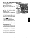
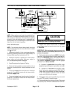
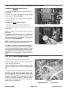
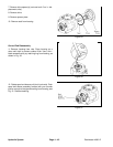
1. Lift control test port 2. Lift control valve
Figure 22
1
2
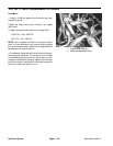
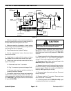
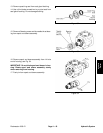
1. Lift control test port 2. Test gauge
Figure 23
1
2
TEST NO. 9: Check Charge Pressure
1. Hydraulic oil must be at operating temperature.
2. Install a 1000 psi gauge onto the quick disconnect at
the top of the pump package.
3. Start the engine and position throttle at idle
(1200 rpm). Tester reading should be from 75 to 150
PSI.
4. If there is no pressure or pressure is too low, check for
restriction in pump intake line. Inspect charge relief
valve and valve seat. Check for sheared charge pump
key. Disassemble charge pump and check for internal
damage or worn parts. If the charge pump is in good
condition (no scoring, scratches, or excessive wear),
the general condition of the piston pump might be sus-
pected of wear and inefficiency.
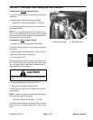
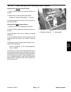
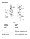
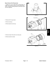
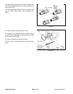
1. Charge press. test port 2. Traction pump
Figure 24
1
2