


Reelmaster 4000–D
Page 4 – 9
Hydraulic System
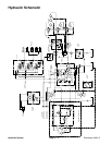
Hydraulic Flow Diagrams (2WD Machines Only)
General Pump Flow
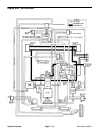
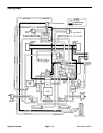
Refer to “Engine Run – No Functions” Flow Diagram
The traction, reel, and auxiliary pumps are directly
coupled to the engine. With all controls in neutral and the
engine running, the steer–lift pump draws oil through the
suction line from the reservoir. Priority output flow is di-
rected to the steering function. Excess flow exits the
secondary output of the pump and is directed to the lift
valve.
The flow continues through the lift valve where it meets
the counterbalance valve. The counterbalance valve
“super–charges” the incoming oil before allowing the oil
to continue on its return path back to the sump tank. The
counterbalance pressure may be monitored at pressure
tap port 3.
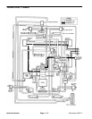
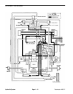
The oil pressure provided by the counterbalance valve
will be used to reduce the cutting unit weight on the turf
during the mowing function.
After joining with oil returning from other functions
through the drain block, the oil flows through the oil cool-
er to dissipate heat from the hydraulic system and then
through the filter to collect any particles in the hydraulic
system.
Clean oil is collected at the filter by the charge pump.
This oil is used to maintain a supply of oil to the closed–
loop traction circuit to prevent cavitation. The charge
pressure is regulated by a relief internal to the traction
pump. The charge pressure may be monitored at the
pressure tap port on top of the charge pump.
Oil collected by the reel pump is directed to the reel
speed valve and split into two variable flows. Primary oil
is directed to the reel “On–Off” control valve. With the
valve in the “Off” position, the oil is returned directly to
the drain block. The remaining oil will also return to the
tank through the drain block.
Hydraulic
System