


Reelmaster 4000–D Page 7 – 15 Cutting Units
Front and Rear Rollers
Note: Front and rear rollers can be removed and
installed in the same manner.
Removal
Note: Front and rear rollers can be removed using ei-
ther of two methods.
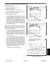
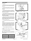
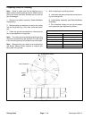
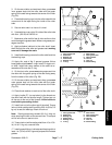
1. Remove roller adjustment housing from side plate
(Fig. 26).
A. Remove mounting fasteners securing both
guards and roller adjustment housings to the side
plate.
B. Pull housings from roller shafts.
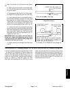
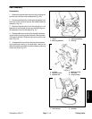
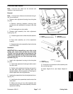
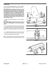
2. Remove collar assembly from roller adjustment
housing (Fig. 27)
A. Unscrew upper cone nut from the collar assemb-
ly.
B. Drop collar assembly out of the adjustment
housing.
C. Separate both collar assemblies from both ends
of the roller shaft.
Installation
IMPORTANT:When assembling a new roller to the
cutting unit, mount roller so that the roller shaft
”locknut” is on the right side of the cutting unit. (As
viewed by the operator sitting on seat of machine).
This prevents the lock nut from loosening during
operation (Fig. 27).
1. Install roller adjustment housing to the side plate
(Fig. 26).
A. Install roller adjustment housings to both ends of
the roller shaft.
B. Position roller adjustment housing and guard to
the side plate. Make sure mounting holes are
aligned properly. Secure guards and housings to
the side plate with mounting fasteners.
2. Install collar assembly to the roller adjustment hous-
ing (Fig. 27)
A. Install both collar assemblies to both ends of the
roller shaft.
B. Make sure cone nut is on collar assembly with
the cone facing up. Slide collar assembly into each
adjustment housing.
1. Guard
2. Roller adjustment housing
3. Side plate
4. Mounting fasteners
Figure 26
1. Cone nut
2. Collar assembly
3. Lock nut
Figure 27
C. Thread cone nut onto each collar assembly with
the cone facing down.
D. Adjust height–of–cut (see Adjust Height–of–
Cut).
Cutting Units